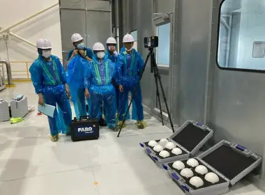


Scan to BIM with Underground Utility Detection – RMIT International School, District 7
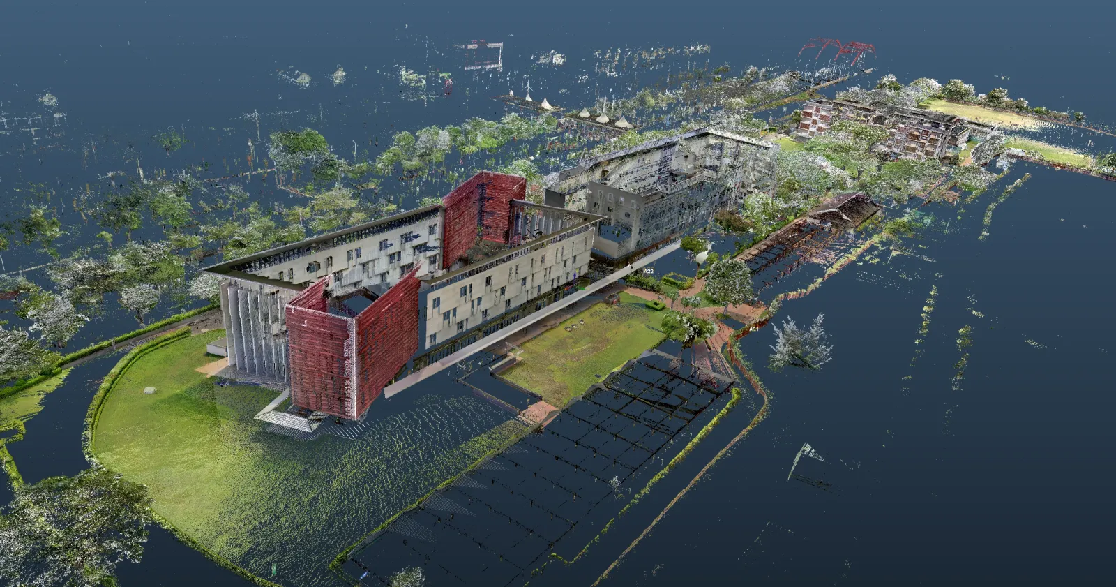
3DSCAN delivered a Scan to BIM project combining underground utility detection and topographic survey at RMIT International School, District 7, Ho Chi Minh City, across a 10-hectare site with 35,000 m² of detailed scanning. Three technologies ran in parallel: the Leica RTC360 for 3D laser scanning above ground, GPR (Ground Penetrating Radar) for locating buried utilities at depths of 0.3–5 m, and an EM Locator to confirm the position of cables and metallic pipes. All data was merged into a single Scan to BIM model at LOD 300, completed in 10 days, supporting renovation design and expansion of the campus technical infrastructure.
Request a Scan to BIM & utility detection consultation
1. The problem: renovation design on an operating campus
The project aimed to build a comprehensive 3D model of the RMIT International School campus, covering architecture, structure, underground technical systems and existing topography at once, as the basis for renovation and expansion design plus master planning. A dataset describing only what sits above ground cannot meet that requirement.
The reason lies in the nature of renovation work: every added utility — new power, water supply, drainage, telecom lines, extended yards — requires excavation into ground that already carries live buried services. Without subsurface data, designers are forced to assume, and a wrong assumption becomes a strike on a power or water line during construction.
- Location: RMIT International School, District 7, Ho Chi Minh City.
- Total site area: 10 ha (100,000 m²).
- Detailed scan area: 35,000 m², including buildings, yards, green areas and technical systems.
- Equipment: Leica RTC360 (3D laser scanning), GPR, EM Locator, GNSS RTK.
- Data purpose: renovation design, additional technical infrastructure, landscape upgrade planning.
2. Method selection for each data layer
No single instrument captures all three layers above. A laser only scans what light can reach, radar penetrates the ground but cannot definitively distinguish materials, and GNSS provides the coordinate framework but no detailed geometry. The three methods complement one another, on the condition that all of them are tied into one common coordinate system.
Method applied to each data layer
| Data layer | Equipment | Why it was chosen |
|---|---|---|
| Architecture, structure, yards, landscape | Leica RTC360 – 1,200 setups | 2,000,000 points per second and 3D point accuracy of 1.9 mm at 10 m (Leica Geosystems datasheet) — full coverage of 35,000 m² within a 10-day schedule |
| Buried pipes, cables, drainage | GPR + EM Locator | GPR traces alignment and depth across 0.3–5 m with no excavation; the EM Locator independently confirms metallic runs |
| Topography, elevation, coordinate framework | GNSS RTK | Brings the point cloud and the utility network into the same coordinate and elevation system used for design |
3. Field data acquisition
Field work was split into three coordinated packages: 3D laser scanning, underground utility detection and topographic survey. The order matters, because utility detection results must be marked onto geometry that has already been scanned, rather than recorded separately and matched later.
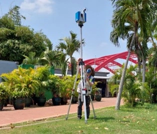
a) 3D laser scanning with the Leica RTC360 – 1,200 setups
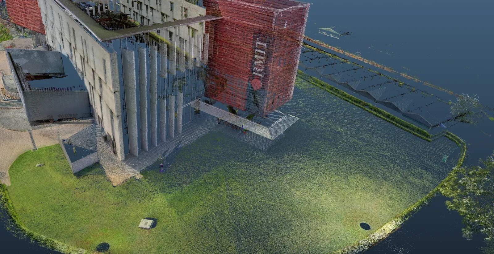
- 1,200 scan setups were completed with the Leica RTC360 at a point density of more than 10 million points per m², covering buildings, yards, green areas and technical items across 35,000 m².
- Registration used Cloud-to-Cloud alignment with RMS error held below 5 mm across the whole setup network.
- Data was exported in E57, RCP and LGS for BIM modelling and for sharing with the design team.
A density of 1,200 setups over 35,000 m² reflects the nature of a school campus: many building blocks, corridors, canopies and trees block the line of sight, so each setup only "sees" a narrow zone — markedly different from as-built 3D laser scanning of a single structure.
b) Underground detection with GPR and electromagnetic locating
- GPR (Ground Penetrating Radar) was used to locate buried pipes, power cables and drainage lines at depths of 0.3–5 m.
- An EM Locator confirmed the position of cables and metallic pipes.
- Every detected run was marked on a 3D map linked directly to the above-ground model.
Principle diagram: the surface layer from laser scanning and the 0.3–5 m utility layer from GPR and EM Locator merged into one coordinate system.
c) Topographic survey with GNSS RTK
- Control points and elevations were measured with GNSS RTK to establish the coordinate framework for the full 10-hectare site.
- Laser scan data combined with the terrain model produced a surface model accurate to ±10 mm.
On larger, more open sites this terrain layer is usually supplemented by UAV 3D topographic survey; on a campus with dense trees and tall blocks such as RMIT, laser scan data remains the primary geometric source.
4. From raw data to the BIM LOD 300 model
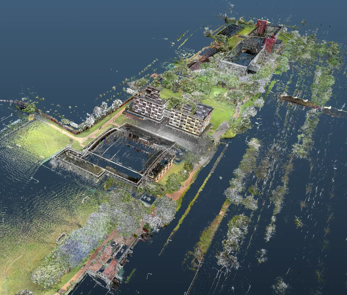
All three data layers were integrated into a single BIM LOD 300 model in Revit, reflecting both the surface condition and the underground network. The processing chain follows the six steps below, each with its own check before moving on.
Six steps: 1,200 scan setups → registration at RMS below 5 mm → GPR and EM Locator detection → GNSS RTK coordinate framework → surface model at ±10 mm → BIM LOD 300 in Revit.
LOD 300 was selected because it is detailed enough for the design team to place dimensions, levels and component positions directly on the model, and to run infrastructure clash detection between new design items and existing buried services. If subsurface data existed only as separate 2D drawings, that clash check could not be automated.
“The value of this project is not a good-looking point cloud. It is that the power cable found with the EM Locator and the concrete slab scanned with the RTC360 sit in the same coordinate system. Only then can a single excavation marked on a design drawing be checked against the services below it.”
— Phan Tien Duyen, Director, 3DSCAN Technology Company Limited
5. Quality control and the tolerances achieved
Quality was controlled against four independent thresholds, one per data layer. The figures below are the project's acceptance tolerances, not the nominal specifications of the instruments.
Tolerances controlled in the project
| Item | Threshold achieved | What it means for design |
|---|---|---|
| Cloud-to-Cloud registration | RMS < 5 mm | A 1,200-setup network does not drift when chained from one building block to the next |
| Delivered point cloud | ±5 mm | Component dimensions can be re-measured on the data instead of on site |
| Terrain surface model | ±10 mm | Finished levels and yard drainage gradients can be calculated |
| GPR / EM detection | 0.3–5 m depth band | Risk zones are delineated before the excavation plan is drawn |
6. Deliverables after 10 days
The project was completed in 10 days and delivered a comprehensive digital dataset in four groups:
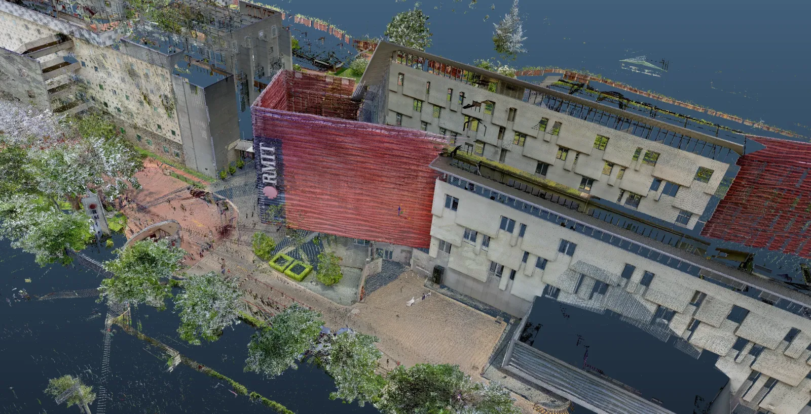
- Point cloud accurate to ±5 mm covering the entire 35,000 m² scan area, in E57, RCP and LGS formats.
- Underground utility map covering power, water, drainage and telecom, built from GPR and EM data.
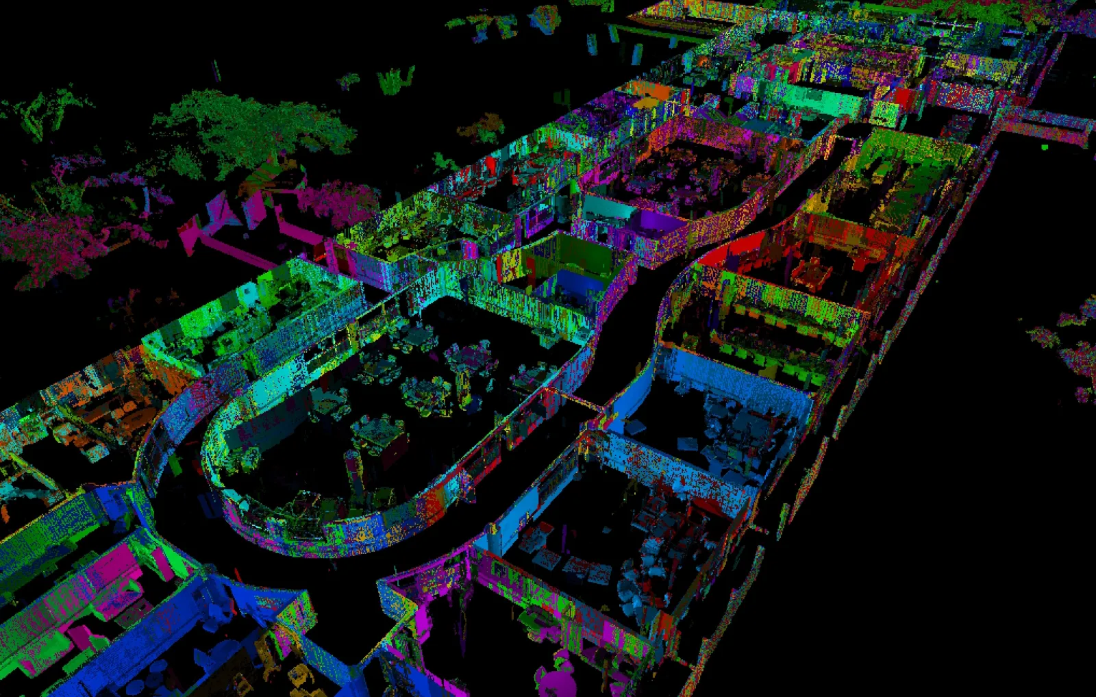
- BIM LOD 300 model representing architecture, terrain and buried technical infrastructure.
- Integrated GIS dataset supporting campus-wide upgrade planning — the same class of data 3DSCAN handles in its planning data conversion to GIS service.
7. What the dataset solves for the owner
Combining 3D laser scanning with GPR detection lets the owner establish the exact condition of the technical infrastructure, reduce construction risk and work from a solid data base during renovation and expansion design. Specifically:
- Clash detection on the model: new utility runs are trialled in Revit against existing buried services before construction drawings are issued.
- Controlled excavation planning: zones holding power cables and water pipes at 0.3–5 m depth are delineated in advance, not discovered once the excavator is already down.
- Level and yard drainage design: based on a ±10 mm surface model rather than interpolation between scattered spot levels.
- Campus-wide landscape planning: the GIS dataset allows options to be assessed across all 10 hectares, not only inside the area under renovation.
8. Lessons learned from the project
GPR needs a second instrument to confirm its findings. Ground penetrating radar returns a reflected signal, and reading that signal as "plastic pipe" or "metal pipe" is not always conclusive. That is why the EM Locator was on site: for metallic runs and power cables, electromagnetic locating gives an independent confirmation of position.
Setup count depends on line of sight, not on area. 1,200 setups for 35,000 m² is a high density, driven by the many blocks, corridors, canopies and trees obstructing the view. When planning a similar project, setup quantities must be derived from the number of obstructions, not from the square metres shown on a map.
A common coordinate system is a prerequisite, not a finishing step. If the subsurface layer and the surface layer are captured independently and only then fitted together, the discrepancy between the two layers exceeds the internal accuracy of either one. On this project the GNSS RTK framework was established first and every subsequent dataset was tied into it — the same approach 3DSCAN applies when building 3D models with UAV and laser scanning on large sites.
Conclusion
The Scan to BIM and underground utility detection project at RMIT International School, District 7 is a representative example of the comprehensive as-built survey solution 3DSCAN provides: integrating 3D laser scanning – GPR – EM Locator – GNSS RTK within a single coordinate system to deliver an accurate, consistent dataset that lets owners and designers decide with confidence, cut costs and keep renovation works safe. 3DSCAN Technology Company Limited is headquartered in Ho Chi Minh City and has delivered 3D scanning, Scan to BIM and topographic survey projects in provinces and cities across Vietnam.
Related projects by 3DSCAN
- 3D LiDAR scanning for buildings — point data capture for structures still in operation.
- 3D model of the Tan Hue Vien resort — a large site with many separate elements.
- 3D laser scanning for Xa Loi Pagoda conservation — as-built scanning in an actively used space.
- Scan to BIM service — workflow, LOD levels and deliverables.
Need an as-built survey that combines Scan to BIM with underground utility detection? 3DSCAN provides 3D laser scanning, GPR detection, EM locating and GNSS survey at high accuracy, suited to renovation, expansion and technical infrastructure planning projects.
Contact 3DSCAN Hotline: 0938 309 808 · Email: lienhe@3dscan.vn