

Architectural As-Built 3D Laser Scanning in Ho Chi Minh City
3DSCAN Technology Co., Ltd. (headquartered in Ho Chi Minh City, Vietnam) provides architectural as-built laser scanning services: terrestrial laser scanners capture the complete geometry of a structure as a point cloud with a 3D point accuracy of 1.9 mm at 10 m (per the Leica Geosystems datasheet for the RTC360). From this data, the team produces 2D as-built drawings (DWG/PDF), 3D models and BIM As-Built models. A typical mid-size building completes field work in 1–2 days and receives deliverables within 2–7 days. This service is the mandatory first step for most renovation, structural inspection, as-built documentation and Scan to BIM projects.
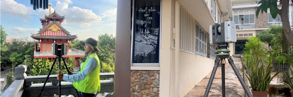
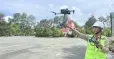
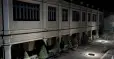
RTC360 Laser Scanner As-Built Survey — Daughters of Charity of Saint Vincent de Paul, Betania Community, Bãi Dâu
What Is Architectural As-Built Laser Scanning?
Architectural as-built laser scanning is a non-contact, non-destructive surveying method: the scanner emits a laser beam that sweeps 360° around its axis, recording millions of coordinate points on building surfaces every second. The result is not a drawing — it is a measurable 3D digital replica of the structure, from which any dimension can be extracted later without returning to site.
The fundamental difference from manual measurement lies here: manual methods record only the dimensions the surveyor thinks they will need. Laser scanning records everything the beam touches. So when the design changes direction, the existing data remains valid — this is why a single scan campaign can serve multiple purposes: design, construction, inspection, heritage conservation and facility management.
Five technical reasons laser scanning replaces manual surveying
- Millimetre-level accuracy: 3D point accuracy of 1.9 mm at 10 m and 2.9 mm at 20 m with the Leica RTC360, compared to centimetre-level errors from tape measures and manual data entry.
- No detail left behind: ornamental features, curved vaults, concealed beams and MEP systems running above the ceiling are all captured simultaneously alongside the architecture and structure.
- Shorter time on site: field surveys take hours to a few days instead of several weeks, minimising disruption to ongoing building operations.
- Safer for engineers: no need to climb scaffolding or access elevated areas, silos, tanks or live operational zones.
- Data reusable throughout the lifecycle: a single point cloud can produce 2D drawings, 3D models, BIM models, As-Built documentation and a browser-based online viewer.
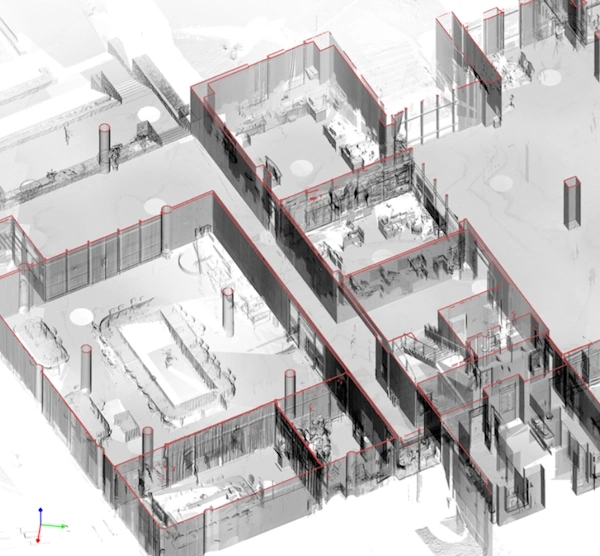
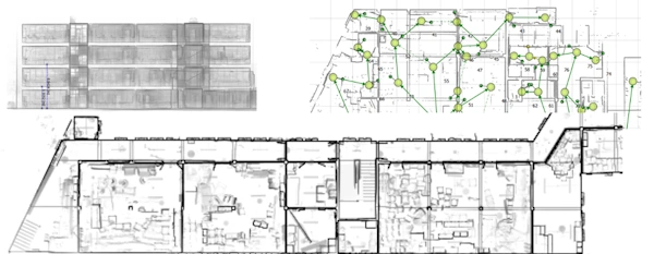
Converting Point Cloud Data into 2D Drawings
3D Laser Scanning vs. Manual As-Built Surveying
The table below compares the two methods across eight criteria commonly used by building owners to make their decision. Key takeaway: the biggest gap is not in accuracy but in data reusability — the cost of scanning is amortised across every downstream task.
Comparison of two as-built surveying methods
| Criterion | Traditional Manual Survey | 3D Laser Scanning |
|---|---|---|
| Method | Tape measure, handheld laser, total station; manual note-taking and data entry | Terrestrial laser scanner captures millions of 3D points per second, non-contact |
| Accuracy | Centimetre-level error, dependent on individual skill and site conditions | 3D point accuracy of 1.9 mm at 10 m; 2.9 mm at 20 m (Leica RTC360 datasheet) |
| Time on site | Multiple days to several weeks for a large building | A few hours to 1–2 days depending on the number of scan stations required |
| Level of detail | Captures only key dimensions; ornamental features, vaults and deflections are difficult to record | Records every surface within line of sight, including actual deformations and deviations |
| Visualisation | 2D drawings only; spatial context is hard to convey | 3D model and online viewer, shareable with all stakeholders simultaneously |
| Worker safety | Requires direct access to elevated areas, confined spaces and live operational zones | Remote measurement; engineers remain in safe positions |
| Deliverables | Basic 2D drawings (DWG, PDF) | Point cloud (E57, RCP, LAS), 2D drawings, 3D model, BIM model, As-Built records |
| Reusability | Tied to a single purpose; design changes often require a new survey | Used throughout survey – design – construction – inspection – operation |
3DSCAN's Architectural Laser Scanning Workflow
3DSCAN follows a fixed five-step process, where station registration quality control is the step that determines the accuracy of the entire dataset. Total turnaround from site entry to final delivery is 2–7 days, depending on floor area, complexity and the type of deliverables required.
Step 1 - Receive and Analyse Requirements
The survey engineer establishes the intended use of the data — renovation design, structural inspection, As-Built records or BIM modelling — because each purpose demands a different level of detail. A building needing floor plans for an interior renovation and a factory needing a BIM model at LOD 300 will have entirely different scan plans in terms of station count and point density.
Step 2 - Plan Scan Stations
The plan determines scanner positions, total station count and the overlap between adjacent stations. Overlap is the decisive factor: a station that shares no common area with its neighbour cannot be registered, forcing a return to site. In buildings with many small rooms or winding corridors, the station count grows faster than the floor area.
Step 3 - On-Site Laser Scanning
The scanner is placed at each planned station in sequence. Engineers check the data on site after every group of stations to detect blind spots, signal noise from reflective surfaces or insufficient overlap — fixing issues on site is far cheaper than discovering them back in the office.
Step 4 - Point Cloud Processing and Quality Control
Data is processed using specialised software (Leica Cyclone Register, Autodesk ReCap, CloudCompare) through four stages:
- Registration: all scan stations are brought into a single unified coordinate system.
- Registration error control: 3DSCAN maintains overlap deviation below 3 mm for standard architectural projects.
- Noise filtering: removal of pedestrians, vehicles, temporary objects and noise points caused by glass or polished metal surfaces.
- Control point alignment: the model is tied to the site coordinate system or the national VN2000 datum when the project requires legal validity.
"The quality of a scan dataset is not determined at the time of scanning, but at the time of registration. Every scanner delivers point accuracy of a few millimetres, but if the overlap between stations is insufficient, the accumulated error across dozens of stations can grow to several centimetres — and then the model still looks good, still works for viewing, but can no longer be used for fabricating components."
— Phan Tien Duyen, Director, 3DSCAN Technology Co., Ltd.
Step 5 - Model Building and Delivery
From the calibrated point cloud, engineers produce 2D drawings, 3D models or BIM models as required. All deliverables undergo a QA/QC check against the source data before handover. For projects requiring a complete building information model, the workflow continues through the Scan to BIM service at LOD 200–350.
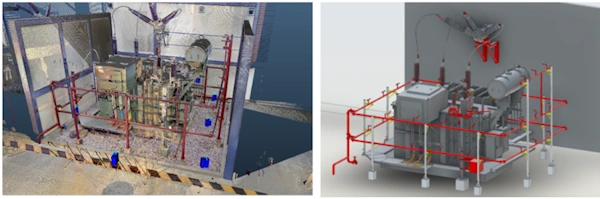
Digitising Power Station Components in Detail
Laser Scanning Equipment Used by 3DSCAN
3DSCAN selects equipment based on building characteristics rather than using one scanner for every project. Churches, factories and large open spaces call for long-range static scanners; corridors, staircases, basements and confined areas use handheld SLAM devices because setting up fixed stations is impractical.
Equipment specifications per manufacturer datasheets
| Equipment | Scan Speed | Accuracy | Best Suited For |
|---|---|---|---|
| Leica RTC360 Static 3D Laser Scanner |
2,000,000 pts/sec | 3D point accuracy 1.9 mm at 10 m; 2.9 mm at 20 m | Churches, factories, large-scale public buildings |
| Z+F IMAGER 5016 Long-Range Static 3D Scanner |
Up to approx. 1,000,000 pts/sec | Millimetre-level linearity error, range up to 360 m | High-detail interiors, large multi-storey atriums |
| FARO Focus M70 Compact Static 3D Scanner |
Up to 488,000 pts/sec | Ranging error ±3 mm, range up to 70 m | Residential buildings, offices, small-to-mid-size structures |
| ComNav LS600 Handheld SLAM LiDAR |
Up to 640,000 pts/sec | Centimetre-level accuracy, continuous scanning while walking | Corridors, staircases, basements, confined spaces with many turns |
Specifications sourced from datasheets by Leica Geosystems, Zoller+Fröhlich, FARO Technologies and ComNav Technology. Actual project accuracy also depends on the registration plan and site conditions.
When a project includes exterior facades, roofs or large campuses, 3DSCAN supplements the data with UAV photogrammetry to complete surfaces that the terrestrial scanner cannot see — this combined approach is detailed in the 3D modelling with UAV and Laser Scan service.
Deliverables
Clients receive datasets in the following formats, selected to match the practical needs of their project:
- Registered point cloud: E57, RCP/RCS, LAS/LAZ, PTS — calibrated raw data, reusable for any future purpose.
- 2D as-built drawings: DWG and PDF including floor plans, sections and elevations at the required datum levels.
- 3D model: OBJ, FBX for presentations, renderings and simulations.
- BIM model: Revit (RVT) or IFC at LOD 200–350 depending on scope of contract.
- Online viewer: Web Viewer and VR360, shareable via link with all stakeholders — no specialist software required.
- Technical report: survey methodology, scan station diagram and registration error statistics.
Practical Applications of As-Built Scan Data
- As-built documentation: accurately reconstruct architecture, structure and building services as input for design documentation.
- Renovation and extension design: As-Built data reflects the true current state after years of modifications, avoiding the common situation where archive drawings no longer match reality.
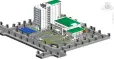
- BIM modelling: convert the point cloud into a Revit or IFC model for multi-discipline coordination and lifecycle management.
- Fire safety planning: accurately measured floor plans and clear heights enable correct placement of equipment and evacuation routes to code requirements.
- Structural inspection and monitoring: measure tilt, deflection, structural deformation and compare as-built conditions against design.
- Volumetric calculation: for material stockpiles, silos and tanks, 3D data enables volume calculation by 3D scanning instead of geometric estimation.
- Heritage conservation: preserve the exact geometry and ornamentation before restoration — the specialised service is described under heritage conservation surveying.
Notable Projects
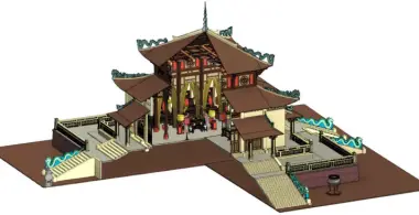
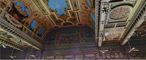
- HCMC People's Committee & People's Council Headquarters: full digitisation of architecture and structure of this heritage building for conservation, research and decorative restoration.
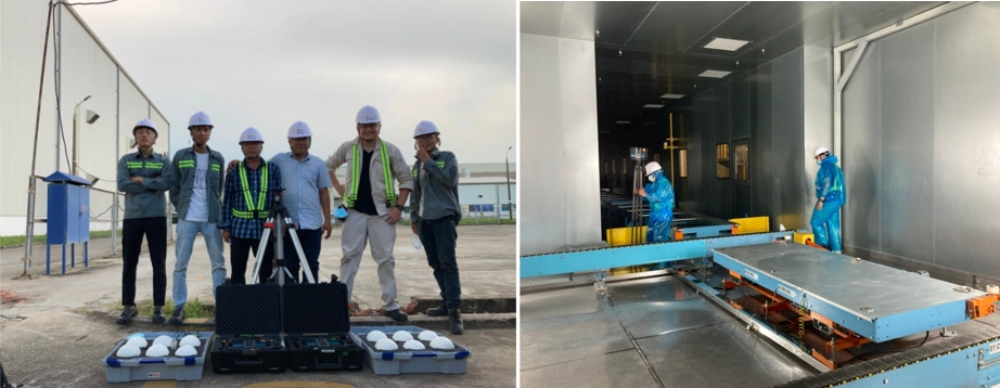
- Ford Factory, Hai Duong: as-built scan of the factory and production line, BIM model for renovation design while the plant remained in operation.
- 120 m Antenna Tower — HCMC: tilt and structural deformation inspection at positions inaccessible by direct contact.
- Cement warehouses, silos and industrial tanks: volumetric calculation, structural safety inspection and as-built documentation.
- Kindergarten in Thu Duc City, HCMC: full architecture – structure – MEP BIM model as the basis for renovation design.
Why Choose 3DSCAN
3DSCAN competes on accuracy and the verifiability of data, not on low pricing. Every deliverable package includes registration error statistics so that the client and reviewing authority can independently verify the results, rather than receiving a visually impressive model with no way to know how much it deviates from reality.
- Right equipment for each building type: static scanners Leica RTC360, Z+F IMAGER 5016, FARO Focus M70 and handheld SLAM ComNav LS600, combined with UAV LiDAR and GNSS RTK when the project requires a national coordinate system.
- Dedicated survey and BIM engineering teams: two separate operational groups - field and data processing - so that quality control is independent from data acquisition.
- QA/QC process with measurable metrics: registration error kept below 3 mm for standard architectural projects, with supporting verification records.
- International technical collaboration: partnership with a French counterpart for point cloud processing on the Leica Cyclone Register platform.
Related 3DSCAN projects
- 3D Laser Scanning of Hanoi Cathedral — digitising vault architecture and decorative details for heritage conservation records.
- 3D Laser Scanning for Xa Loi Pagoda Conservation — as-built scan of an active place of worship in Ho Chi Minh City.
- Scan to BIM with Underground Utility Survey at RMIT District 7 — combining above-ground as-built scanning with underground infrastructure in a single coordinate system.
- Professional 3D LiDAR Scanning for Buildings — scope of deployment, equipment and deliverables.
Need an as-built scan for your building — for drawings, renovation design or BIM modelling? Send 3DSCAN the location and floor area and we will provide a scanning plan, estimated station count and delivery timeline.
Contact 3DSCAN Hotline: 0938 309 808 · Email: lienhe@3dscan.vn