

Scan to BIM in a live factory: 700 scan setups and an LOD 350 model at First Solar Cu Chi
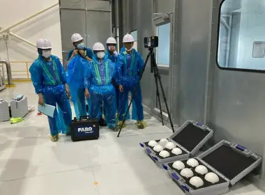
3DSCAN Technology Co., Ltd. delivered a Scan to BIM project for the First Solar photovoltaic module plant in Cu Chi Industrial Park, Ho Chi Minh City, supporting the design of a production line upgrade and expansion. The entire production hall and its service corridors were captured with a Leica RTC360 terrestrial laser scanner across 700 scan setups, registered with the Cloud-to-Cloud algorithm at an average RMS of 4.2 mm, and modelled into a Revit LOD 350 model accurate to ±5 mm against the as-found condition. Total duration was 6 days: 1 day of field scanning and 5 days of processing and modelling. This is a typical industrial Scan to BIM project, where site conditions are more demanding than the accuracy of the instrument.
Request industrial Scan to BIM advice
Free space in a factory is measured in clearances, not in square metres
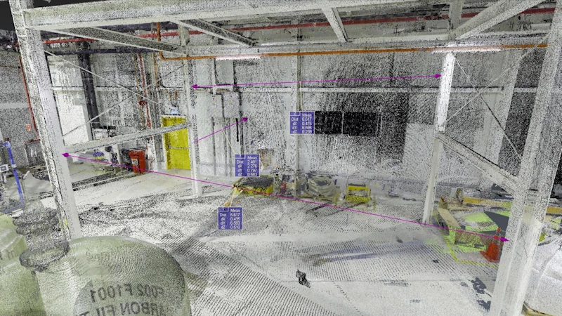
How many square metres a new line needs is the easy question. The hard one is which pipe crosses that space, at what level the beam sits, how many centimetres the cable tray leaves below the ceiling. Supports and equipment frames get fabricated to dimensions taken from the old records, then foul a branch pipe the records never showed, and the cost lands on taking the work apart again. A tape and a total station capture only the points the surveyor thinks of in time; with pipework running in layers overhead, getting up to the point you need to measure is a task of its own.
Why a static laser scanner was chosen for this hall
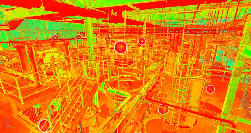
The scope covered the production hall and service corridors, with steel framing, columns, beams, floors, ceilings, pipework and suspended cabling: an indoor space with many layers of occlusion and many slender members high overhead. For conditions like these, 3DSCAN chose 3D LiDAR scanning of built structures with a static scanner. The reason is point accuracy: according to the Leica Geosystems datasheet, the Leica RTC360 delivers a 3D point accuracy of 1.9 mm at 10 m, 2.9 mm at 20 m and 5.3 mm at 40 m, a maximum rate of 2,000,000 points per second and a range of 0.5 to 130 m. A handheld SLAM scanner moves faster but carries far higher error, not enough for an LOD 350 model; a UAV cannot work inside a closed-roof hall. The RTC360 laser is Class 1 under IEC 60825-1:2014, eye-safe, so the instrument can be set up in areas where workers are passing.
One day on site: 700 setups and the 60–70% overlap rule
Before any instrument goes down, the technician walks the floor plan to define the scan route. The working rule is that each setup must share 60–70% of its field of view with the adjacent setup. This is a technical condition, not a recommendation: no control points or targets were placed in the hall, so the overlapping volume between two setups is the only data available to register the two point clouds.
Holding that ratio is harder in an industrial hall than in a building. Production lines, electrical cabinets, tanks and service walls divide the space into pockets that occlude one another, so the scan route has to run denser and double back more often. That is what drives the figure of 700 scan setups, with raw data exported as .LGS and .E57.
The Cloud-to-Cloud registration principle and the accuracy figures of the First Solar Cu Chi project
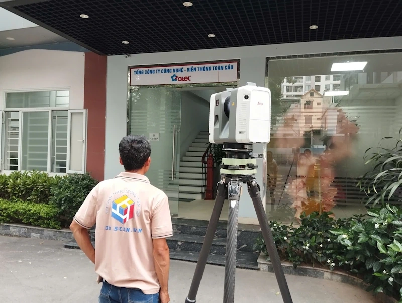
[Site photograph required: engineer setting up the RTC360 inside the hall]
Registering 700 point clouds Cloud-to-Cloud: how far it goes
All 700 setups were registered in Leica Cyclone REGISTER 360 using Cloud-to-Cloud registration and the ICP (Iterative Closest Point) algorithm: instead of matching targets, ICP repeatedly finds the closest point pairs between two clouds, then rotates and translates until the total distance is minimised. The average error after registration was RMS 4.2 mm, below the 5 mm RMS acceptance threshold.
ICP only converges correctly when the shared volume has distinctive geometry. A blank flat wall or a row of identical columns can let the algorithm settle one bay out of place while still reporting a small error. The overlap zone is therefore chosen where members do not repeat: machine corners, pipe branch clusters, equipment plinths.
Choosing scan resolution against the deliverable
Resolution governs both model quality and field hours, so it must be fixed before the first setup. The RTC360 offers three settings:
Choosing a scan setting against the deliverable
| Resolution (at 10 m) | Suited to | Trade-off |
|---|---|---|
| 3 mm | Connection details, flanges, slender members | Slowest, largest data volume; hard to apply across 700 setups |
| 6 mm | BIM LOD 300–350 for structure and MEP, clash detection | Under 2 minutes per full dome setup including the spherical HDR image |
| 12 mm | Overall as-found condition, floor and ceiling levels | Fastest, but misses branch pipes and hanger rods |
Resolutions of 3 mm, 6 mm and 12 mm at 10 m and the scan time are taken from the Leica RTC360 datasheet (Leica Geosystems).
“In a factory that keeps running, what decides model quality is not the accuracy of the instrument but the scan route. The scanner gives 1.9 mm point accuracy at 10 m, yet if one setup loses its overlap, the whole branch of data behind it cannot be registered, and there is no fix other than going back to rescan.”
— Phan Tien Duyen, Director, 3DSCAN
Checking with a deviation map before the first element is modelled
After registration, the data is checked with a cloud deviation map: the software compares the registered clouds and colours them by the deviation between them, so poorly matched zones show up immediately. Zones above the threshold are corrected area by area before the data goes forward to BIM modelling. The order matters: model first and discover a misaligned branch afterwards, and every element in that branch has to be rebuilt.
From point cloud to a Revit LOD 350 model
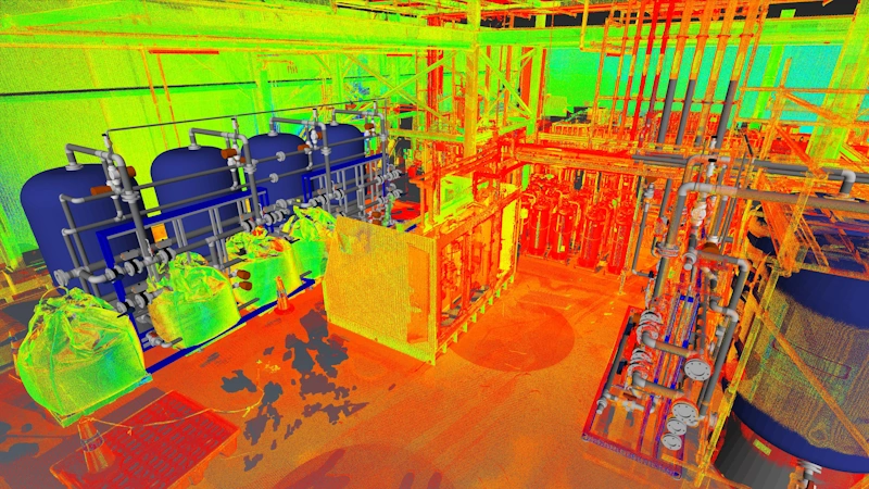
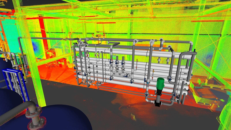
The cleaned data was modelled in Revit at LOD 350, covering architecture, structure and MEP systems. LOD 350 means each element is modelled with its real size, shape and position and also shows its interfaces with other elements, enough to check clashes between new equipment and existing services. The scope covers walls, steel structure, floors, ceilings, service pipes, tanks and cable trays, completed in 5 days. The same approach is applied to 3D laser scanning of as-found architecture and to 3D modelling with UAV and laser scanning.
Deliverables
- Raw point data: .LGS and .E57 for all 700 scan setups.
- Registered point cloud with a registration report showing RMS 4.2 mm.
- Revit LOD 350 model: architecture, steel structure, floors, ceilings, service pipes, tanks, cable trays.
- As-Built drawings exported from the model.
What the design team does with this data
Working on the model and the point cloud, the design team runs spatial analysis to place new equipment, including in high positions that are hard to reach, clash detection in Revit and Navisworks to find collisions between planned equipment and existing pipes and cabling, retrofit design on geometry that matches the as-found condition rather than old drawings, and As-Built drawing output to update the plant records.
Against a conventional survey of the same scope, the programme was about 50% shorter. The largest saving is the number of return trips avoided: the point cloud already holds the points that nobody knew would be needed at the time of scanning.
What the project taught us
The number of setups in a factory scales with occlusion, not with floor area. An empty hall twice the size may need fewer setups than a small hall packed with production lines, so when planning the work, counting the divided pockets tells you more than counting square metres.
Cloud-to-Cloud removes the target placement but shifts the burden onto the scan route. Registration quality depends on whether the operator holds 60–70% overlap and picks the zones with distinctive geometry. That decision is made on site and cannot be corrected in the office.
Conclusion
The Scan to BIM project at the First Solar plant in Cu Chi demonstrates what 3DSCAN can deliver on an industrial site that stays in operation: 700 Leica RTC360 scan setups, Cloud-to-Cloud registration at RMS 4.2 mm, a Revit LOD 350 model accurate to ±5 mm, handed over in 6 days. 3DSCAN is headquartered in Ho Chi Minh City and has delivered 3D scanning and Scan to BIM projects in provinces across Vietnam.
Related projects by 3DSCAN
- Scan to BIM with underground utility detection at RMIT International University, District 7
- 3D LiDAR scanning of built structures: scope of application and deliverables.
- 3D scanning for stockpile volume calculation
- Scan to BIM service: standard workflow and LOD levels.
Does your plant need an as-found record for a retrofit, a line expansion or new equipment? Send 3DSCAN your floor plan and the deliverable you need, and we will propose a Scan to BIM approach with the LOD level, the expected number of scan setups and the programme.
Contact 3DSCAN Hotline: 0938 309 808 · Email: lienhe@3dscan.vn