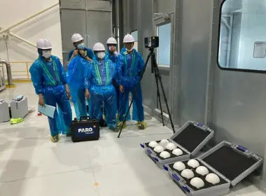


From Point Cloud to BIM: A Scan-to-BIM Workflow with 5 mm Accuracy Control
In industrial plant retrofit and equipment installation projects, the accuracy of existing-condition data directly affects design quality. Even a small deviation in the position of structural elements, equipment, or conveyor systems can lead to design clashes and costly modifications during construction and installation.
At Formosa Ha Tinh, Vietnam, 3DSCAN carried out 3D laser scanning and Scan-to-BIM of a conveyor system for the main contractor, ScanTech – Australia. Existing conditions were captured using a Leica RTC360, processed into a 3D point cloud, and subsequently modeled in Autodesk Revit at LOD300, with a required model accuracy control of 5 mm.
The completed as-existing BIM model provides a reliable spatial reference for engineering design and clash detection, allowing the design team to identify potential conflicts before fabrication and on-site installation.
1) The Challenge: Accurate Existing-Condition Data for Clash-Free Design
Industrial conveyor systems typically consist of complex geometry involving steel structures, support frames, access platforms, equipment, and numerous associated components.
During retrofit projects or the installation of new systems, relying on outdated drawings or incomplete site measurements creates a significant risk of clashes between the new design and existing structures.
- Position discrepancies: existing components may not be located exactly where legacy drawings indicate.
- Dimensional discrepancies: actual dimensions may differ due to construction tolerances or subsequent modifications.
- Incomplete documentation: many existing components may not be represented in the original drawings.
- Complex spatial conditions: congested areas can be difficult to measure comprehensively using conventional methods.
- Risk of rework: clashes may only be discovered after fabrication or during installation.
The objective of the project was therefore not simply to produce a visually impressive 3D model, but to create an as-existing BIM model based on accurately measured site data and suitable for engineering design.
2) High-Accuracy Scan-to-BIM Workflow at Formosa Ha Tinh
2.1 Survey Planning and 3D Scanning Strategy
Before data acquisition, the conveyor system and surrounding structures were reviewed to determine scanner locations, potential occlusions, and the required overlap between scan stations.
For a high-accuracy Scan-to-BIM project, the quality of the final BIM model depends directly on the quality of the point cloud used as its reference. Scan positions were therefore planned to provide sufficient coverage of critical components while minimizing blind spots and occluded areas.
2.2 Data Acquisition with Leica RTC360
3DSCAN used the Leica RTC360 terrestrial laser scanner to capture the geometry of the conveyor system and the surrounding industrial environment.
The laser scanner captures a high density of measurements from visible surfaces, creating a 3D point cloud that digitally represents the physical geometry of the facility at the time of the survey.
Unlike conventional surveying methods that record only selected dimensions or discrete points, a point cloud preserves extensive geometric information about existing conditions. This data can subsequently be revisited, measured, and analyzed throughout the design process.
2.3 Point Cloud Registration and Quality Control
Data collected from individual Leica RTC360 scan stations was registered into a unified point cloud dataset.
At this stage, the point cloud was checked before being transferred to the BIM modeling process to ensure data consistency and to control alignment between individual scan positions.
The workflow followed a simple but critical principle:
Accurate Survey → Reliable Point Cloud → Accurate BIM → Reduced Design Clashes
2.4 Building the LOD300 Revit Model
The processed point cloud was used directly as the geometric reference for creating the LOD300 Autodesk Revit model.
Components within the project scope were modeled according to their actual geometry and position as represented by the point cloud, rather than relying solely on legacy drawings or assumed dimensions.
2.5 Controlling Model Accuracy to 5 mm
One of the key project requirements was to control the deviation between the BIM model and the point cloud within the specified 5 mm tolerance for the modeled elements included in the project scope.
Throughout the BIM modeling and quality-control process, model elements were compared directly against the point cloud captured on site.
- Component position verification.
- Dimensional verification.
- Elevation verification.
- Orientation and inclination checks.
- Geometric comparison between modeled surfaces and point cloud data.
Elements that did not satisfy the required criteria were identified and corrected before final delivery. This quality-control process distinguishes a 3D model created primarily for visualization from a BIM model developed and verified against high-accuracy survey data.
Need 3D Laser Scanning or Scan-to-BIM for an Industrial Facility?
Hotline 0938 309 808 · Email lienhe@3dscan.vn · Contact 3DSCAN
3) From Scan to BIM to Clash Detection
A key purpose of the as-existing BIM model was to provide a reliable data foundation for engineering design and clash detection.
When the as-existing model accurately represents the position and geometry of physical components, the design team can integrate proposed systems into the same BIM environment and assess their compatibility with existing conditions.
- Detect clashes between new equipment and existing structures.
- Verify installation clearances.
- Check access space for operation and maintenance.
- Identify potential conflicts before fabrication.
- Reduce on-site modifications and rework.
In an industrial environment, identifying a clash digitally during the design stage can significantly reduce risk compared with discovering the same conflict after equipment has already been fabricated or delivered to site.
4) Point Cloud-Based Design vs Conventional Existing-Condition Survey
| Criteria | 3D Laser Scanning + Scan-to-BIM | Conventional Existing-Condition Survey |
|---|---|---|
| Existing-condition capture | High-density geometric capture of visible surfaces as a point cloud. | Limited to the points and dimensions recorded during the site survey. |
| Ability to re-measure | Additional measurements can be taken directly from the point cloud. | A return site visit may be required if dimensions are missing. |
| BIM modeling | Modeling based directly on measured existing geometry. | Greater dependence on drawings and individual site measurements. |
| Clash Detection | Effective comparison of new designs against the as-existing BIM environment. | Existing components that were not measured may remain unidentified. |
| Risk of rework | Reduced by identifying potential conflicts during design. | Higher risk when actual site conditions differ from available documentation. |
5) Project Deliverables
- Registered 3D point cloud of the conveyor system and associated project area.
- LOD300 Autodesk Revit model developed from point cloud data.
- As-existing BIM model with 5 mm accuracy control for elements within the defined project scope.
- BIM data for engineering design, multidisciplinary coordination, and clash detection.
6) Formosa Ha Tinh Scan-to-BIM Project Information
| Project | Conveyor System Scan-to-BIM |
| Location | Formosa Ha Tinh, Vietnam |
| Main Contractor | ScanTech – Australia |
| Survey Equipment | Leica RTC360 |
| Technology | Terrestrial Laser Scanning (TLS) |
| Survey Data | 3D Point Cloud |
| BIM Platform | Autodesk Revit |
| Level of Development | LOD300 |
| Required Accuracy Control | 5 mm |
| Purpose | Engineering Design and Clash Detection |
| Scan-to-BIM Provider | 3DSCAN |
7) The Value of Scan-to-BIM Goes Beyond a 3D Model
A BIM model can look highly detailed and visually impressive, but for engineering applications, a more important question is:
“How accurately does the model represent actual site conditions?”
This is the principle behind 3DSCAN's approach to 3D laser scanning and Scan-to-BIM projects.
Laser scanning, point clouds, and BIM should not be treated as three independent products. They form a continuous digital workflow:
Site → 3D Laser Scanning → Point Cloud → Revit LOD300 → QC → BIM for Engineering Design
For the conveyor system project at Formosa Ha Tinh, the entire workflow — from Leica RTC360 scanning to point cloud processing and LOD300 Revit modeling — was developed around the requirement for 5 mm accuracy control, providing a reliable as-existing model for engineering design and clash detection.
High-Accuracy 3D Laser Scanning & Scan-to-BIM – Contact 3DSCAN
Hotline 0938 309 808 · Email lienhe@3dscan.vn · Contact 3DSCAN
FAQ – Frequently Asked Questions
What is Scan-to-BIM?
Scan-to-BIM is a workflow in which 3D survey data, particularly point clouds captured by laser scanners, is used as the basis for developing a BIM model that represents the existing conditions of a facility.
Why use Scan-to-BIM for industrial retrofit projects?
Operational industrial facilities often differ from their original design documentation due to construction tolerances, modifications, maintenance, and equipment upgrades. Scan-to-BIM captures current conditions and provides a BIM environment in which engineers can evaluate new designs against existing structures and equipment.
How was the 5 mm accuracy requirement applied to this project?
During BIM modeling and quality control, elements within the defined project scope were compared against the point cloud to control model deviations within the specified 5 mm requirement.
Is LOD300 suitable for clash detection?
LOD300 can represent the geometry, dimensions, and location of components at a level suitable for many design-coordination applications. When developed from an accurate point cloud, the as-existing model can provide a reliable reference for clash detection according to project requirements.
Can 3DSCAN deliver both point cloud and Revit data?
Yes. Depending on project requirements, deliverables can include processed and registered point clouds, reference datasets, and Autodesk Revit models for engineering design, coordination, and existing-condition management.