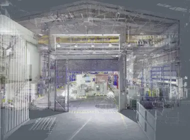


3D Laser Scanning of the Ford Automotive Plant in Hai Duong – For an LOD350 BIM Model
3DSCAN captured the as-built condition of the Ford automotive plant in Hai Duong across 2 ha using two FARO Focus M70 scanners running in parallel, completing more than 3,000 scan stations and delivering an LOD350 BIM model with an overall accuracy under 5 mm. The point cloud was registered with a bridge method combining spheres and cloud-to-cloud, verified against a horizontal and vertical control network on the VN-2000 datum established with a Leica TCR802 and a Leica DNA03. In Scan to BIM for industrial plants, the hardest part is controlling error accumulation across thousands of stations.
Talk to us about plant Scan to BIM
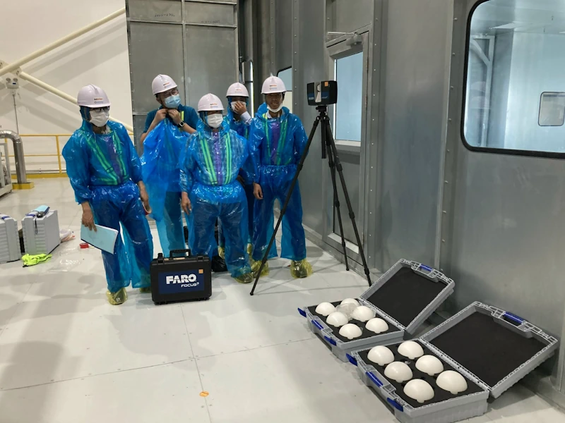
The scanning team following safety protocols before entering the paint booth
The problem in an operating plant
After a few years of operation, an automotive plant rarely matches its design drawings: production lines are added, new services are routed, and most of those changes never make it back into the records. When the owner wants to refurbish or expand, the first task is to measure the as-built condition again. The project requirements were:
- Scope: all technical spaces, production lines and the structural frame of the plant.
- Level of detail: an LOD350 BIM model covering trusses, beams, pipework and machinery.
- Accuracy: overall accuracy under 5 mm, in line with industrial asset-management practice.
- Deliverable data: true-colour point cloud, usable in Revit, Navisworks and ArchiCAD.
These requirements constrain one another: LOD350 forces dense scanning, which pushes the station count into the thousands, and the more stations there are, the harder it is to keep accumulated error below 5 mm.
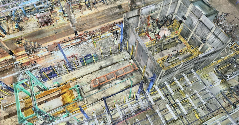
As-built point cloud data of the manufacturing plant
Choosing the method and equipment for 2 ha of workshops
Roof structures, production lines and equipment block the line of sight almost everywhere in the plant. A UAV cannot reach the occluded gaps between machines, and SLAM cannot hold millimetre accuracy inside steel structures, so the project used terrestrial laser scanning (TLS): two FARO Focus M70 units in parallel, with two Leica survey instruments handling the control network. The Focus M70 has a 70 m range, enough for the workshop span and roof height, and it is light enough to move quickly between machine gaps and tight service corridors — decisive when more than 3,000 stations have to be set up.
Equipment used
Equipment deployed at the Ford Hai Duong plant
| Equipment | Qty | Role | Key specifications |
|---|---|---|---|
| FARO Focus M70 | 02 | Scanning workshops, production lines, structural frame | Up to 500,000 points per second, 0.6–70 m range, ±3 mm ranging error, integrated colour camera up to 165 MP, Class 1 laser |
| Leica TCR802 | 01 | Horizontal control network | 2-second angular accuracy |
| Leica DNA03 | 01 | Transferring levels across the site | ±0.3 mm per km double-run (Invar staff) |
Specifications per FARO Technologies and Leica Geosystems datasheets.
Running two scanners at once also lets a whole area be closed out in a single visit — scanning an area halfway and coming back later usually introduces discrepancies, because the production line has moved on.
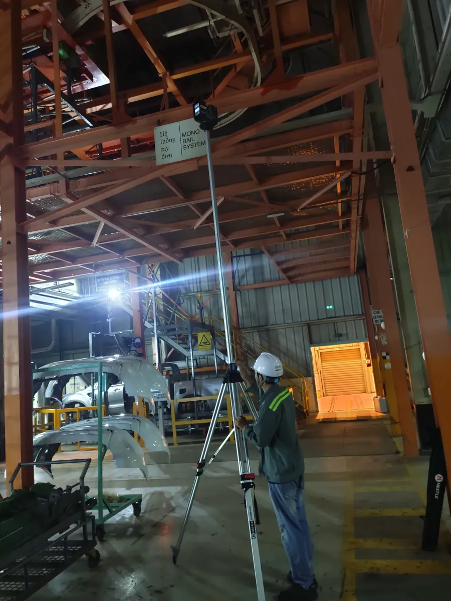
Accessories and equipment used for on-site data capture
Horizontal and vertical control network on the VN-2000 datum
The first task on site was to establish horizontal and vertical control points on the VN-2000 datum across the whole site, before any scanner was switched on. Without an independent control network, thousands of stations are linked only by relative geometry: there is no basis for verifying error, and no way to tie the model into the national coordinate system.
Horizontal positions were measured with a Leica TCR802 total station, levels transferred with a Leica DNA03 digital level (±0.3 mm per km double-run, Invar staff). Both sets of monuments are used to check the point cloud after registration, and to let the design team place the project coordinate system in Revit so that it matches the field.
“On a plant with more than 3,000 stations, the error does not come from the scanner — it comes from how you register. Only with a control network from the TCR802 and DNA03 can a figure under 5 mm actually be verified.”
— Phan Tien Duyen, Director, 3DSCAN
Field data capture: more than 3,000 scan stations
The scan plan was drawn up for the full 2 ha before mobilisation, broken down by workshop, service corridor, walkway and HVAC system. Each area had its own station layout, with sphere positions and bridge routes to areas with no mutual visibility fixed in advance.
In total, more than 3,000 scan stations were captured with two FARO Focus M70 units in parallel. Station spacing was kept short so that the overlap was wide enough for registration, and that density is also what LOD350 requires: the model has to show the true section of every beam, every connection, every level and the real diameter of every pipe run. A gap in the data means a component has to be guessed at during modelling.
Point cloud registration using the bridge method
The data was registered with a bridge method combining spheres and cloud-to-cloud to limit error accumulation. Registering sequentially along a chain means that each joint's error, even just a few millimetres, adds up to centimetres at the far end of the plant. The bridge method splits the data into clusters and uses bridging stations with wide mutual overlap to link those clusters into a closed network, so error is distributed evenly. Spheres are used for joints that need high confidence, cloud-to-cloud for areas rich in geometric features. Once registered, the data is normalised and checked against the Leica TCR802 and DNA03 control points, then cleaned of noise before modelling.
An eight-step workflow: from the VN-2000 control network to an LOD350 BIM model with accuracy under 5 mm
Quality control: overall accuracy under 5 mm
The project achieved an overall accuracy under 5 mm, in line with industrial asset-management practice. Two figures are easily confused: the ±3 mm ranging error is the datasheet specification of a single FARO Focus M70 station, while under 5 mm is the accuracy of the whole data block after more than 3,000 stations have been registered and checked against the control network. It is the second figure that goes into the handover documentation, recorded as an accuracy table with the station layout and scan log so that it can be verified independently.
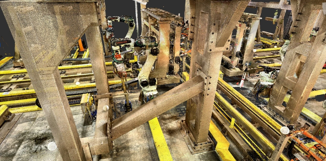
Columns, bracing and welding robots at LOD350 detail; the white spheres are targets set out in advance to bridge clusters of scan positions
Deliverables
- True-colour point cloud: in E57, RCP and LAS formats, with the full colour capture, usable directly in Revit, Navisworks and ArchiCAD.
- LOD350 BIM model: the complete structural frame, floors, ceilings, building services and fixed equipment modelled in detail.
- Plan and section drawings extracted from the point cloud, supporting design and plant re-planning.
- Technical documentation: control point records, accuracy table, station layout and scan log — so the owner can verify the data independently, the approach 3DSCAN applies to every as-built 3D laser scanning project.
What this data solves for the plant
- Verifying the as-built condition of production lines, structure and services, so refurbishment and expansion work from measured data.
- Reducing clash risk when adding new MEP/fit-out systems: collisions between new pipe runs and existing structure show up on the model.
- Creating a digital twin foundation for operations management along CAFM and CMMS lines.
- Meeting BIM requirements for smart factories and Industry 4.0.
What we took away from the project
The control network is not a side task: on a project with a few dozen stations you can get away without one, but on a project with more than 3,000 stations there is nothing left to prove the accuracy with at handover. The expensive part of plant Scan to BIM also sits in the scan plan rather than in scanner hours — the right station layout cuts the number of fill-in stations and return visits. And the LOD has to be fixed before scanning begins, because LOD350 calls for a different station density and scan angles than LOD200.
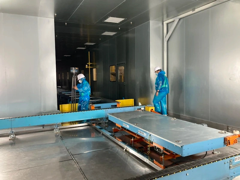
Two engineers scanning inside the paint booth of the automotive plant, in protective clothing
Conclusion
The Ford automotive plant in Hai Duong: 2 ha, more than 3,000 scan stations, an LOD350 BIM model, overall accuracy under 5 mm verified against a control network on the VN-2000 datum. 3DSCAN is headquartered in Ho Chi Minh City and takes on 3D scanning and Scan to BIM projects nationwide. If your plant needs its as-built condition measured before refurbishment or operational digitisation, contact 3DSCAN to discuss an approach for the level of detail you need.
Related projects by 3DSCAN
Need as-built documentation of your plant for refurbishment, MEP additions or a digital twin? 3DSCAN will propose a 3D laser scanning and Scan to BIM approach for the level of detail you require.
Contact 3DSCAN Hotline: 0938 309 808 · Email: lienhe@3dscan.vn