

As-built survey of a church with 3D laser scanning for renovation and repair: Betania Bai Dau project, Vung Tau
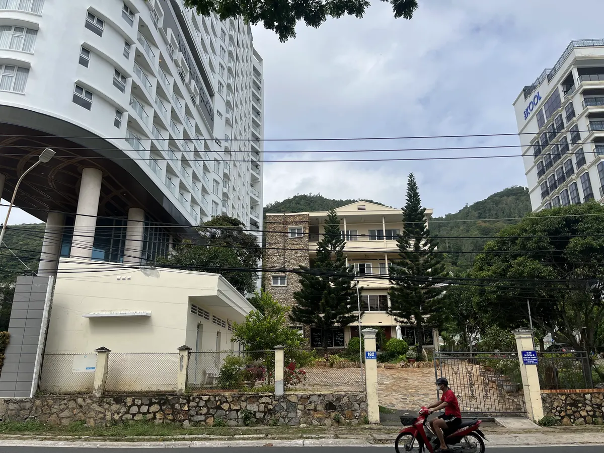
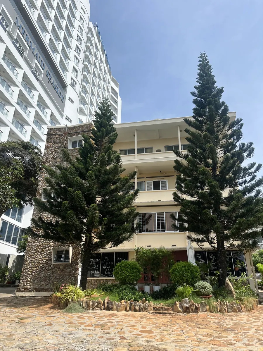
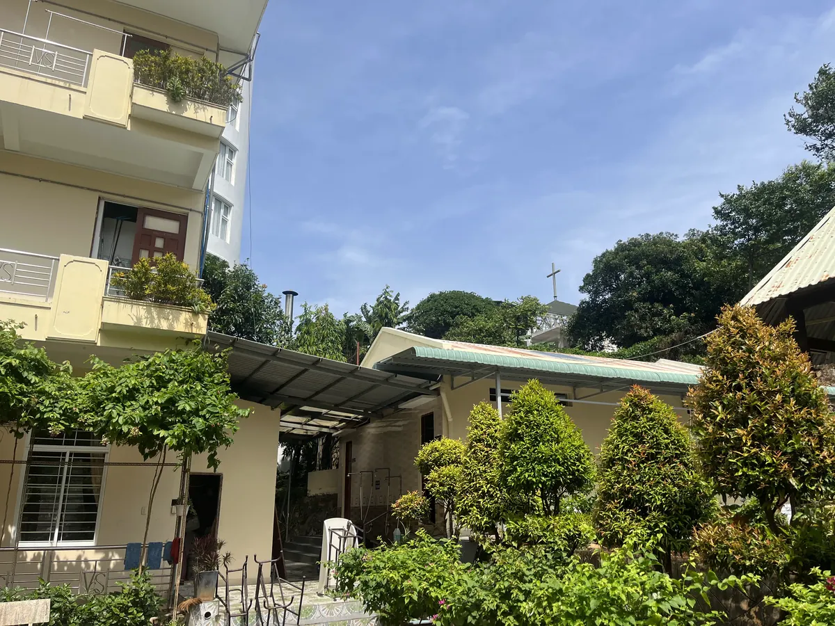
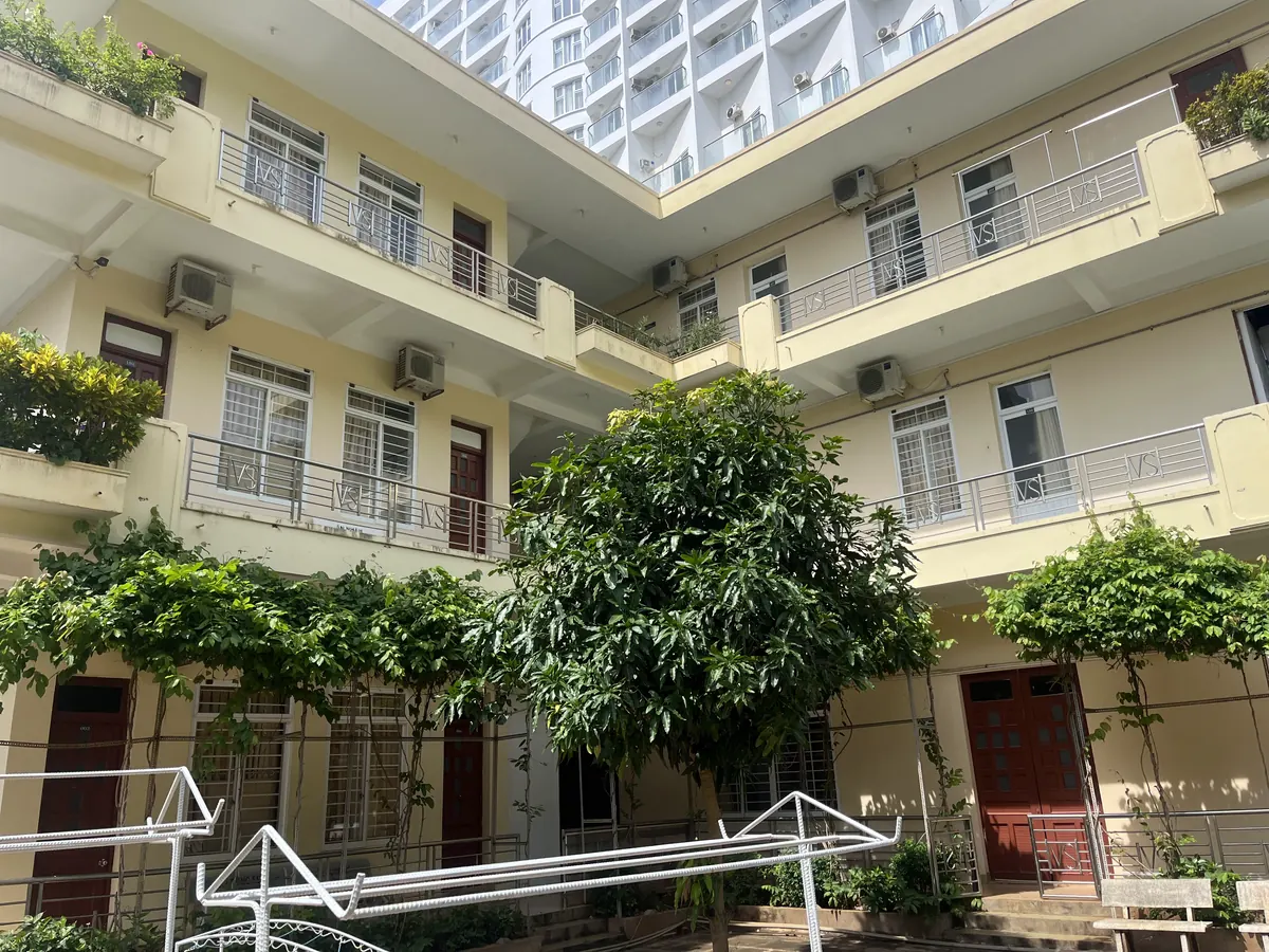
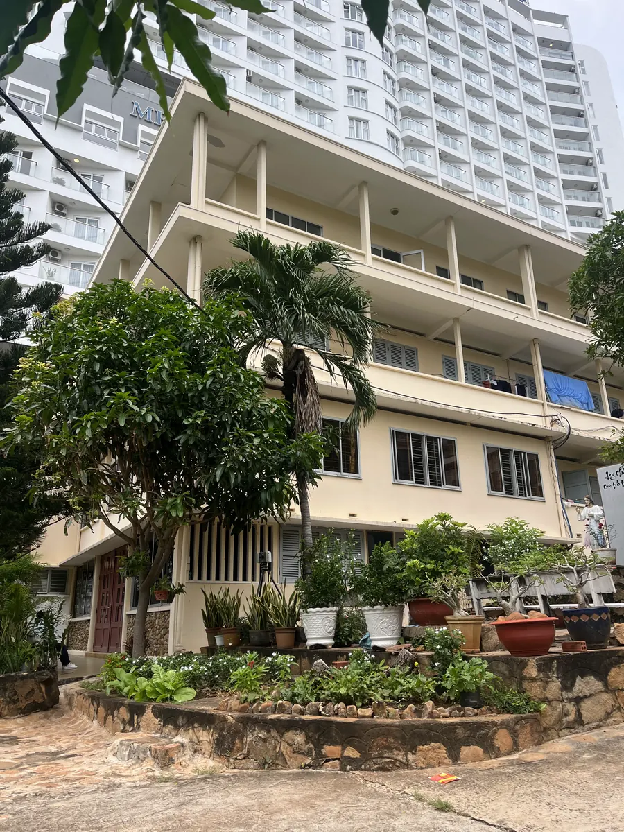
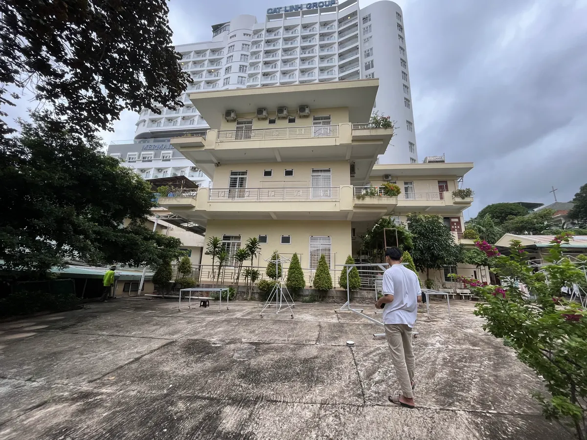
3DSCAN carried out an as-built site and architectural survey of the Daughters of Charity of Saint Vincent de Paul – Betania Bai Dau Community, 162 Tran Phu Street, Vung Tau, as the basis for planning the renovation and repair of the building. The church was built about 30 years ago as a series of stepped blocks, with a total floor area of about 5,000 m². The survey combined 3D laser scanning of existing architecture with a Leica RTC360, static GNSS observations, height transfer by levelling and UAV imagery from above, all tied to a single coordinate and height datum.
Talk to us about an as-built survey
A stepped church: the hard part is tying every level into one drawing set
At Betania Bai Dau, measuring each area was not the difficulty. Making those areas fit together was. The stepped structure creates many floor and roof levels and many transitions between blocks. If each part is surveyed in isolation, plans, elevations and sections easily drift apart when they are joined.
After many years of use, archived drawings (where they exist) do not necessarily reflect the building as it stands after repairs, alterations and later additions. The key requirement of the survey was therefore to establish a single, consistent spatial survey framework, so that the designers could fix the correct position, dimensions and height relationships of every element planned for renovation.
As-built geometry is an input to design. It does not replace a quality inspection or a structural load-capacity assessment.
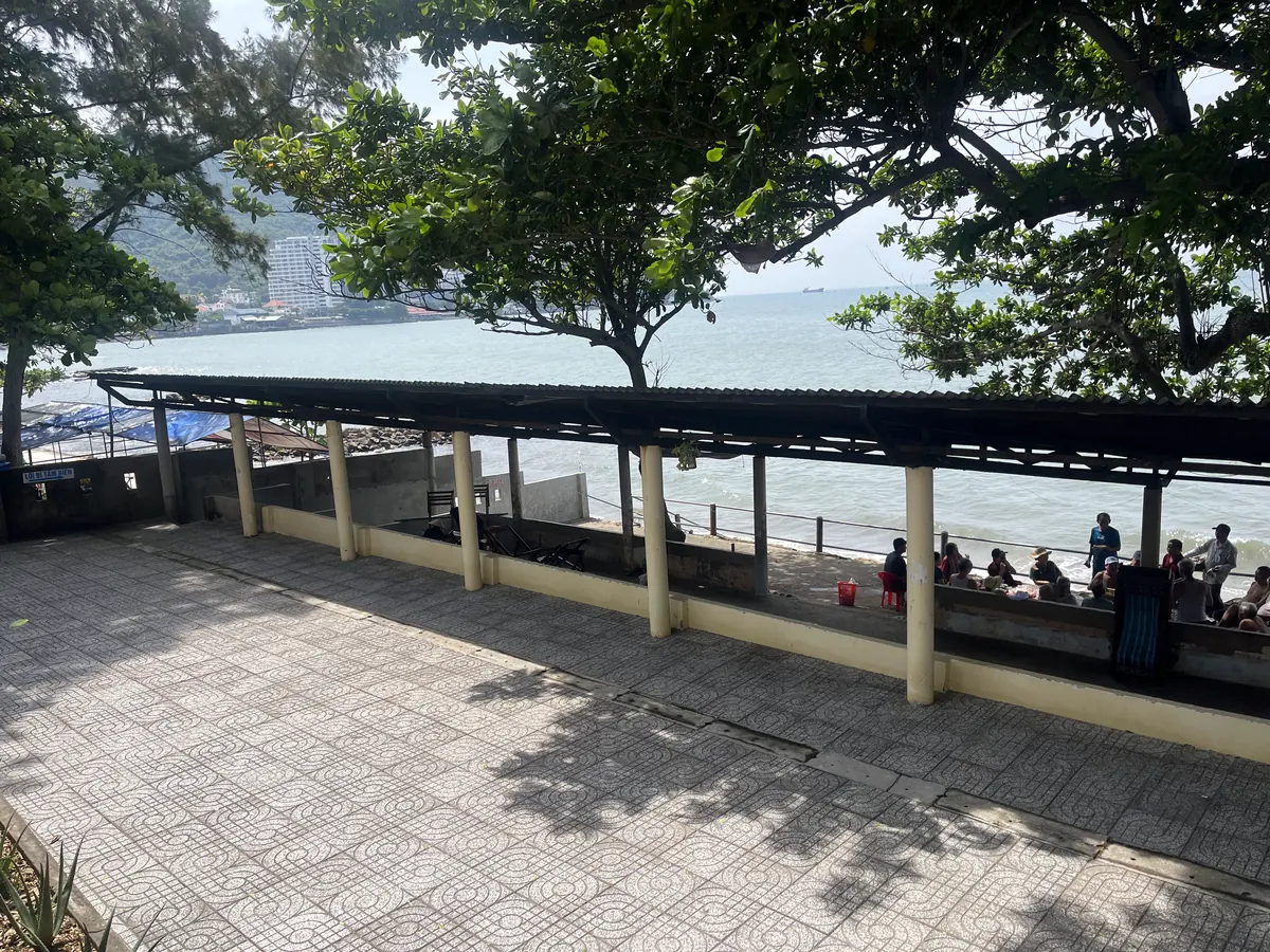
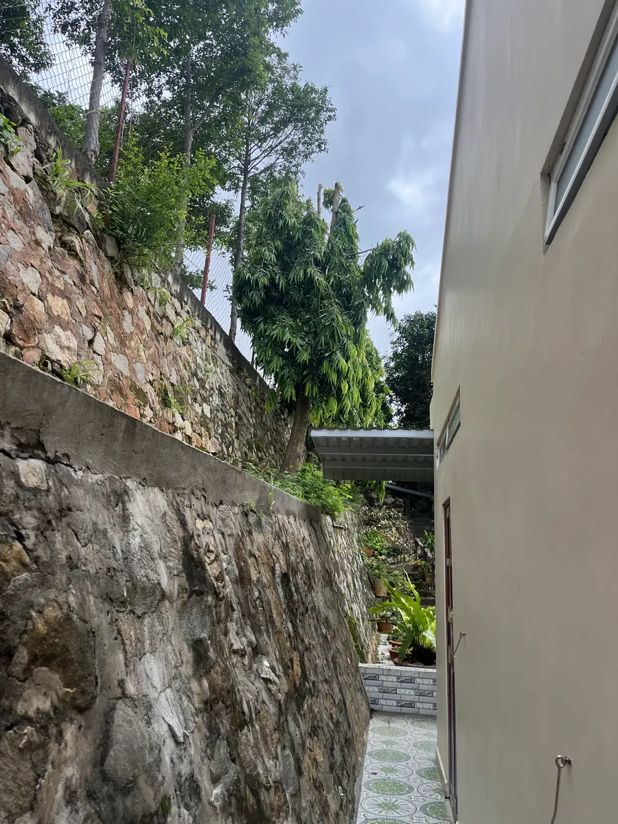
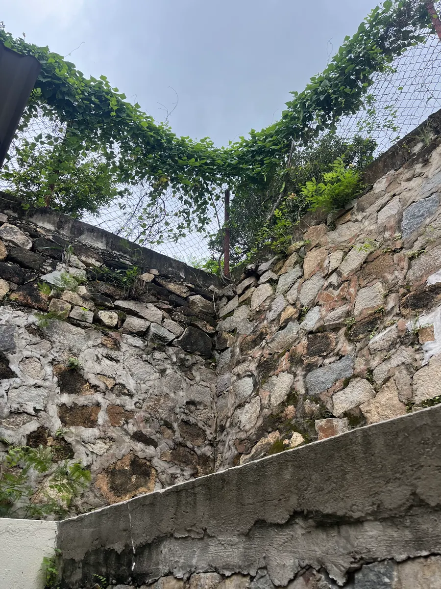
A multi-block campus on sloping rock
7 photos · swipe →
Four survey methods, one shared coordinate and height datum
The data only becomes valuable when all four sources sit on the same reference system.
Schematic diagram, not to the building's scale.
In the diagram, the Leica RTC360 laser scanner records the geometry on each floor level, a levelling line runs from the control mark through the blocks to lock in the height differences, static GNSS positions the building within the campus, and the UAV captures the roofs from above. The output is a set of floor plans for each level, elevations, sections and an as-built site plan on one coordinate and height datum.
Leica RTC360 captures the architectural space in 3D
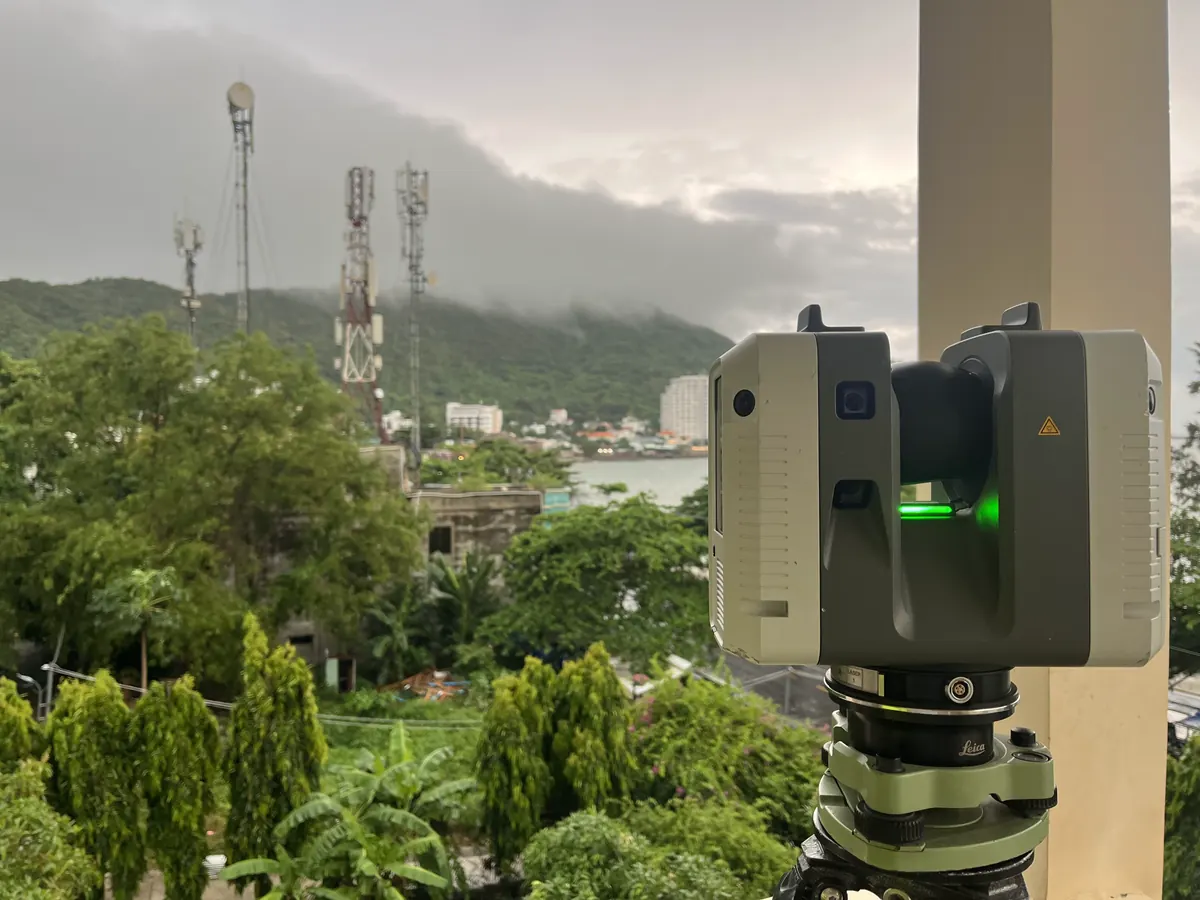
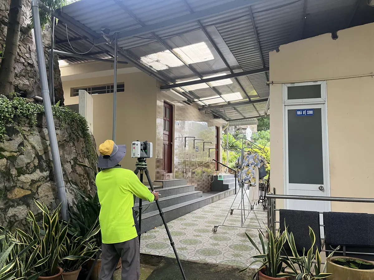
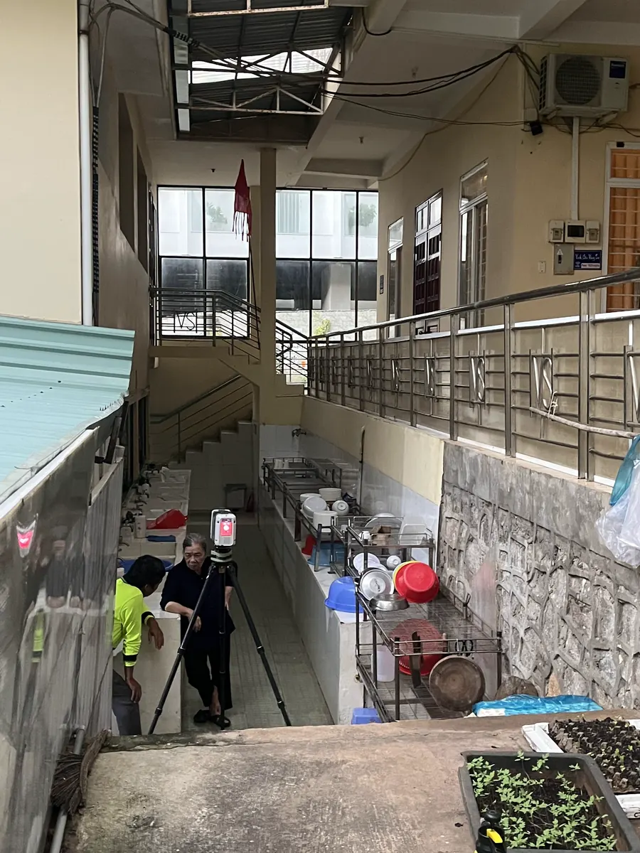
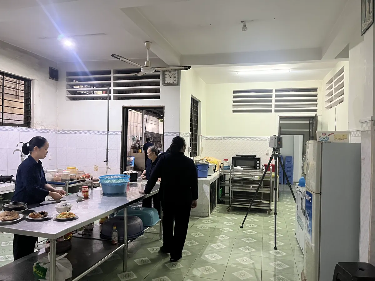
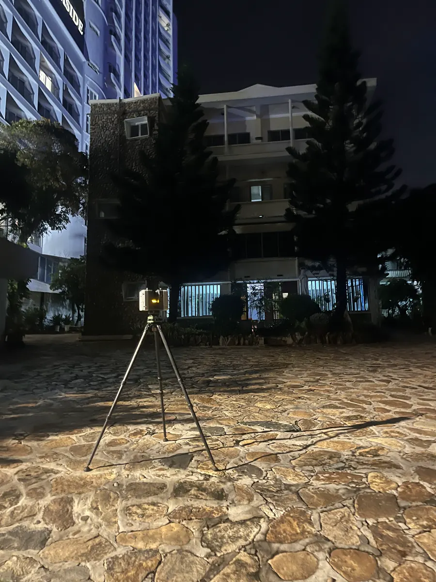
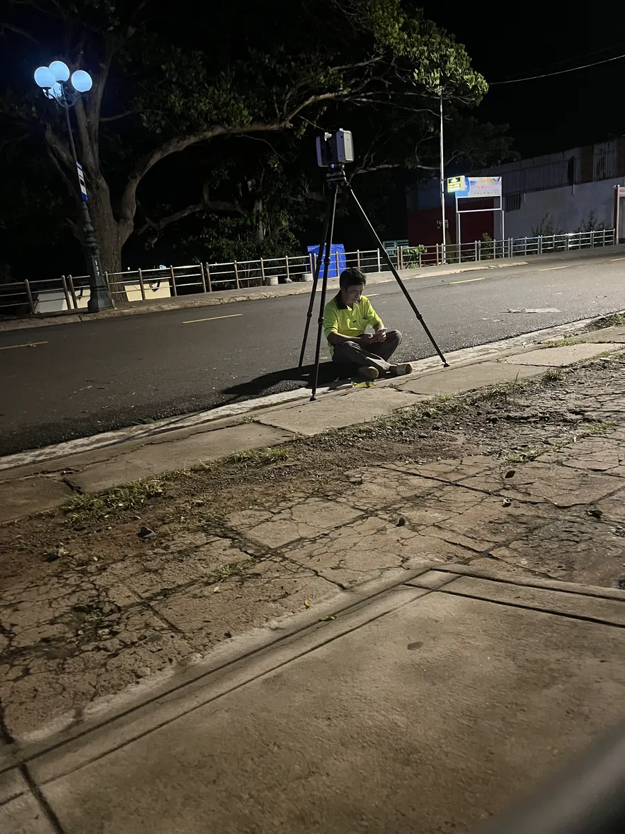
The Leica RTC360 3D laser scanner collects point cloud data from stations with suitable lines of sight. The data records surface shapes, the positions of visible building elements, interior and exterior spaces, the junctions between blocks and the changes in level. According to the Leica Geosystems datasheet, the RTC360 measures up to 2,000,000 points per second with a 3D point accuracy of 1.9 mm at 10 m, and its VIS technology supports on-site registration of scan stations. These are instrument specifications, not the project's acceptance tolerances. From the point cloud, engineers extract as-built floor plans, elevations and sections to suit the design package.
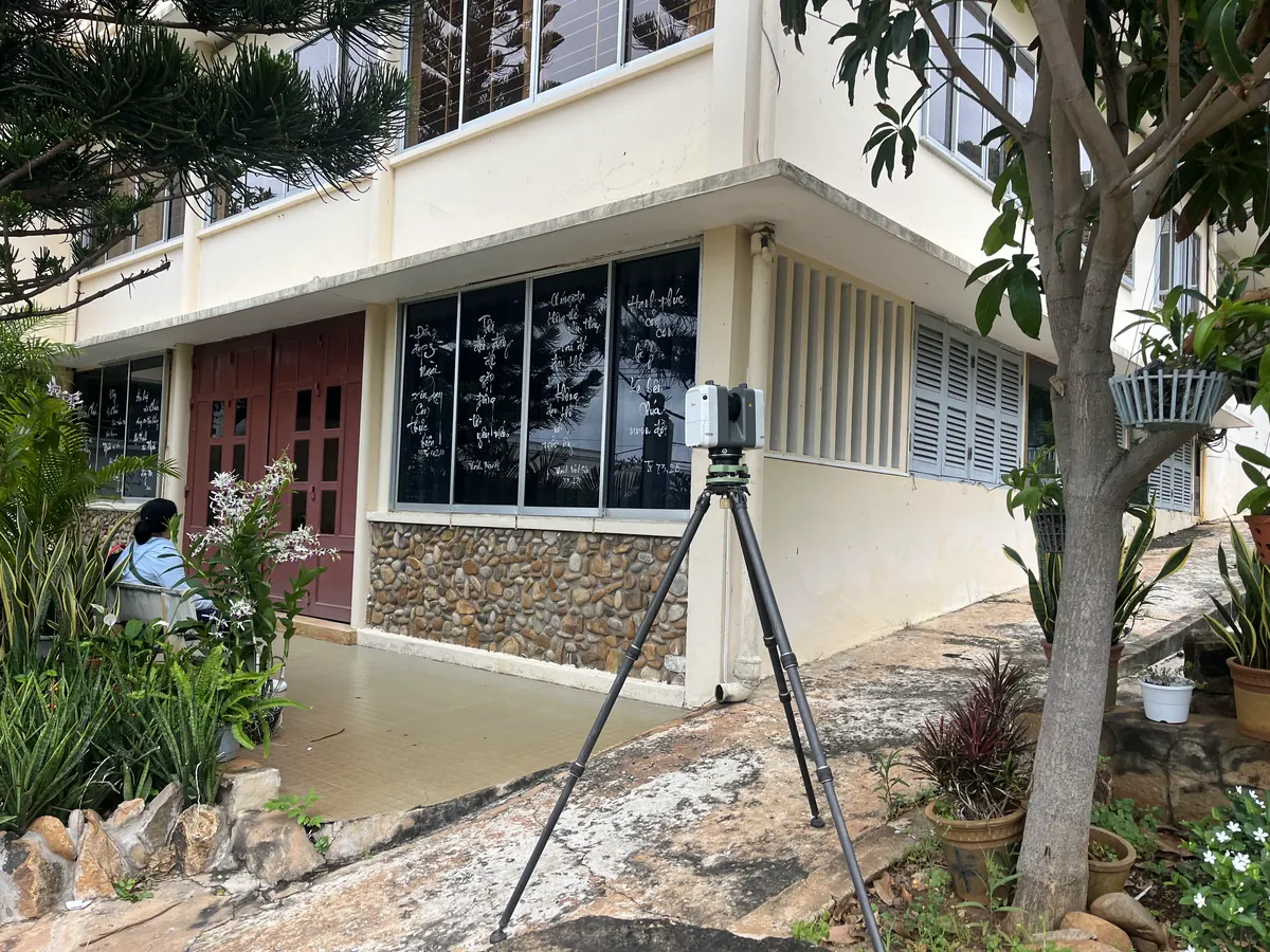
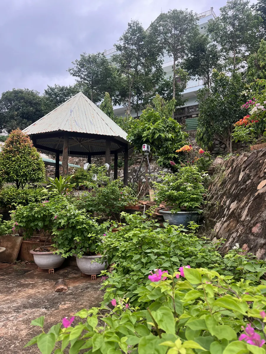
Leica RTC360 laser scanning on site
8 photos · swipe →
Static GNSS places the building in a consistent reference system
Static GNSS observations were used to build the coordinate control network that links survey data from different parts of the building. Before going into the as-built site plan, the observations must be processed, checked and tied to the common reference system.
Levelling keeps the height differences between blocks correct
On a stepped building, heights are where errors most easily creep in when data is combined. Transferring heights by levelling provides an independent check on the height differences between areas. These values are used to tie together floors, courtyards, steps and junctions, limiting discrepancies when the survey datasets are merged.
UAV adds the view of roofs and grounds
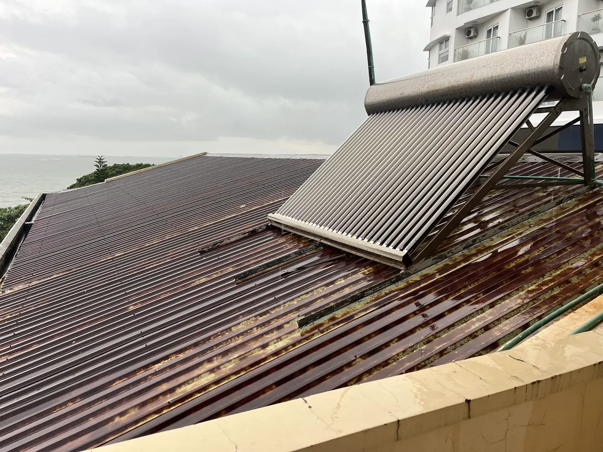
UAV imagery gives an overview from above: the site layout, the roof levels and the relationship between the building and its grounds. It is a supporting data source, familiar from UAV topographic surveying and from combining UAV data with laser scanning, and most useful on roof surfaces that are hard to see from the ground. Occluded areas still need additional checks if they fall within the design scope.
Questions in the renovation brief and the method that answers each
| What the designer needs to know | Primary method | Support / notes |
|---|---|---|
| Shape and dimensions of visible elements; interior and exterior spaces | 3D laser scanning with Leica RTC360 | UAV for exterior surfaces and roofs |
| Position of the building within the campus | Static GNSS | UAV imagery for the overall layout |
| Height differences between courtyards, floors, steps and storeys | Levelling | Cross-checked against the point cloud |
| Roof surfaces and roof levels hard to see from the ground | UAV | Additional checks in occluded areas |
| Material strength, load-bearing capacity | Outside the scope of a geometric survey | Requires a separate specialist inspection |
What the as-built data lets the designers do
After the fieldwork, the data from all methods is checked and organised within one consistent position and height system. Depending on the scope agreed with the design team, the survey database can support:
- As-built site plan: defining the spatial relationship between the building, its grounds and related features.
- Architectural drawings: floor plans for each level, elevations and sections based on the existing geometry.
- Height cross-checks: clarifying the height differences between courtyards, floors, steps, roofs and the junctions between blocks.
- Renovation design support: less reliance on estimated dimensions when planning layouts, repairs or changes of use.
- Digital record: keeping the as-built data for reference and, when needed, developing a Scan to BIM model.
The core value of the solution lies in linking coordinates, heights and 3D geometry, not in any single instrument. It means the renovation design is based on the actual condition of the building.
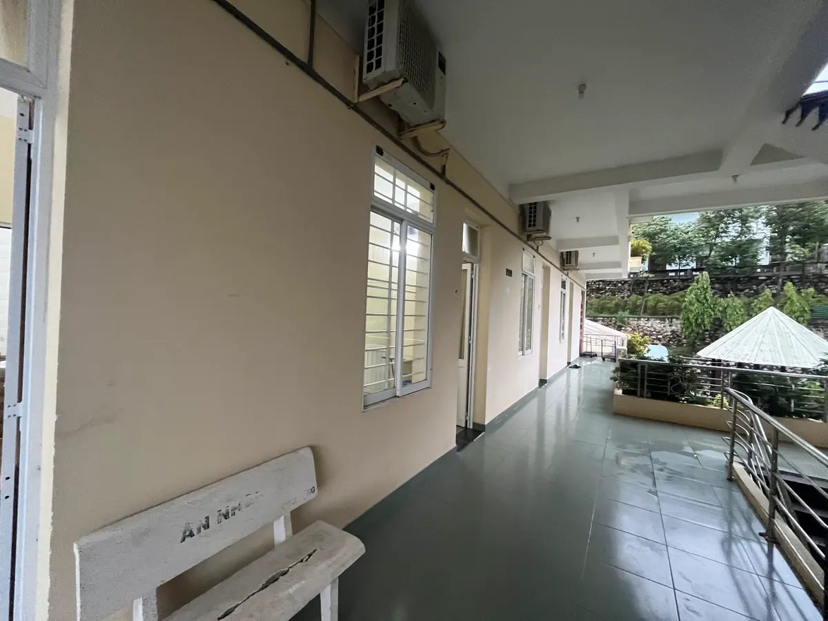
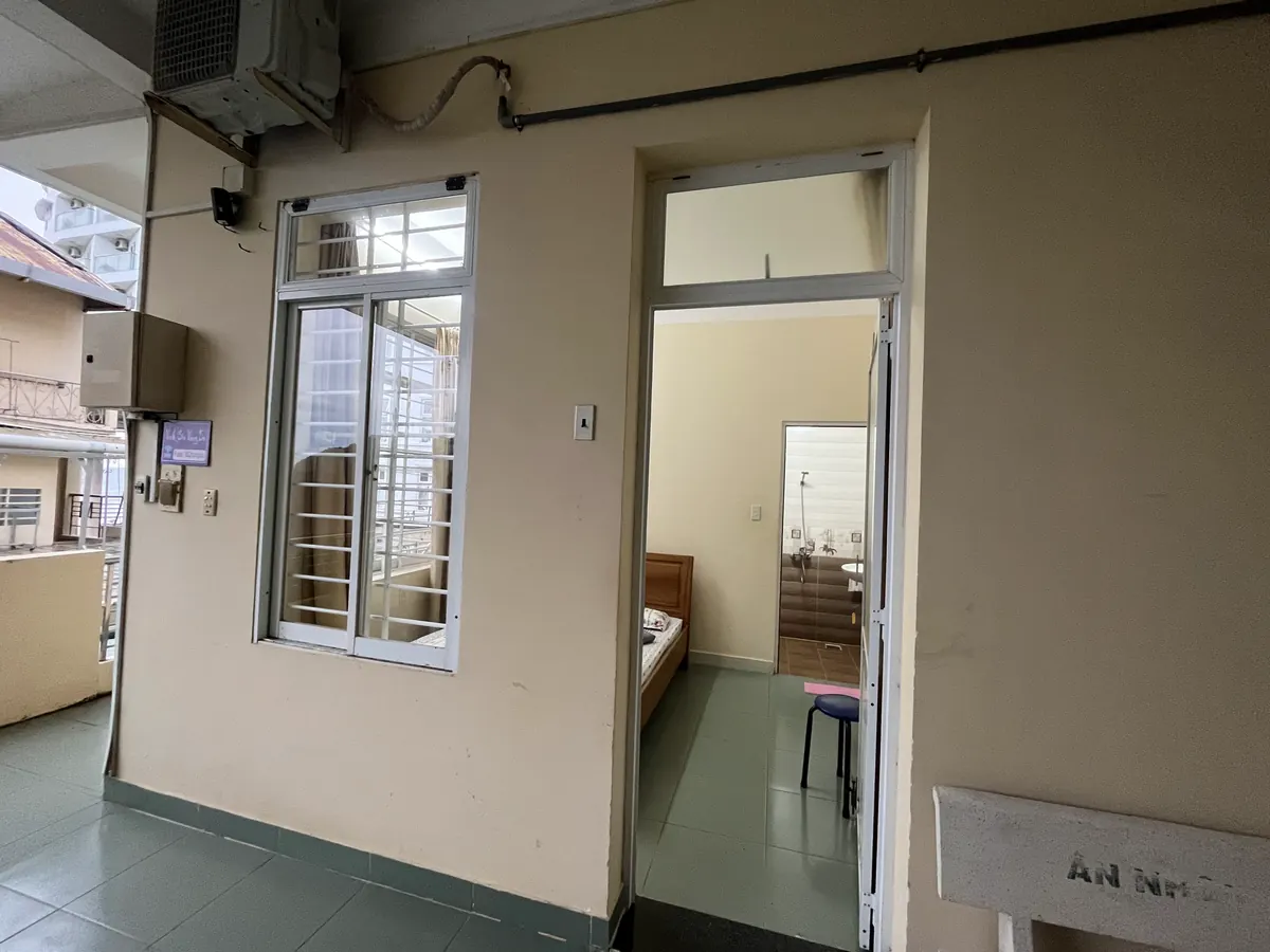
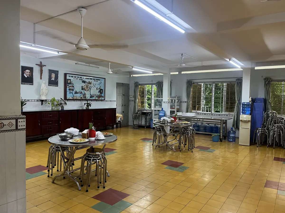
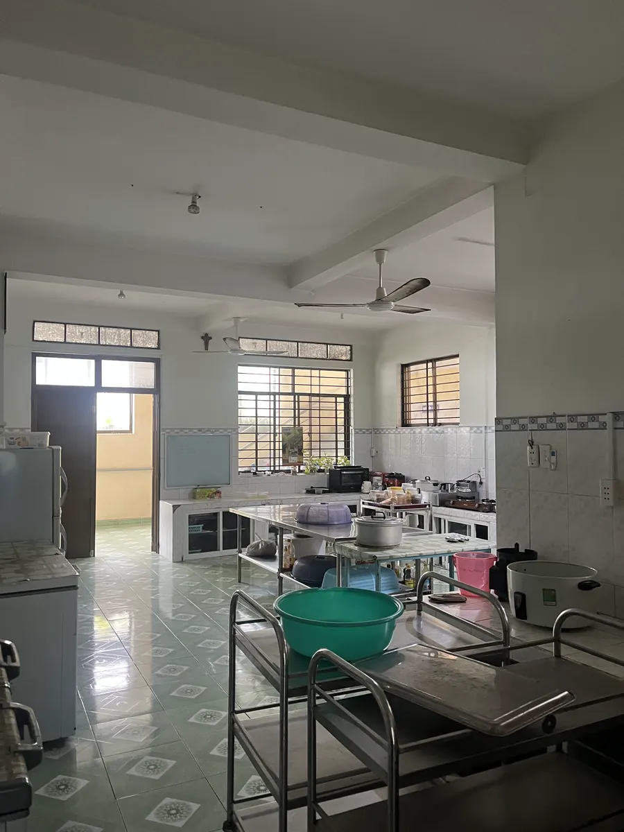
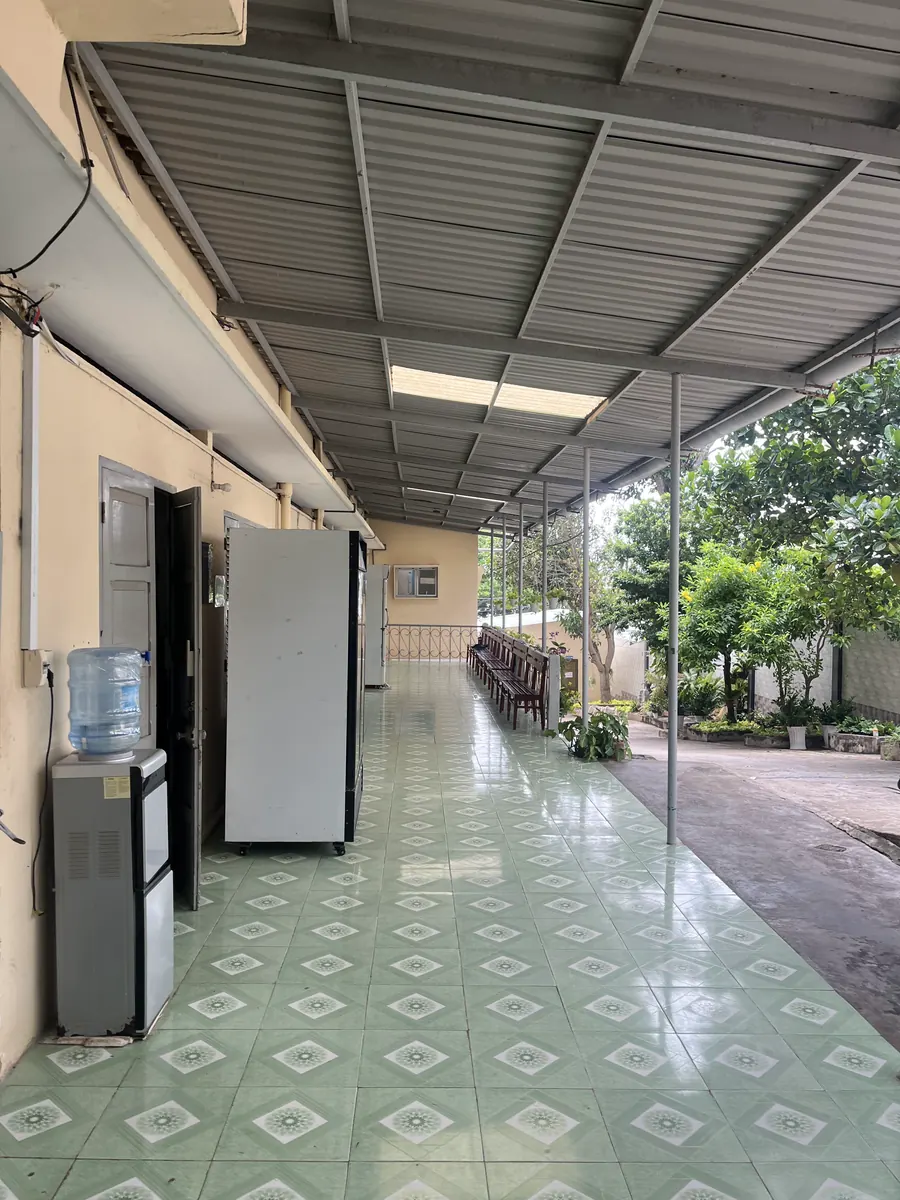
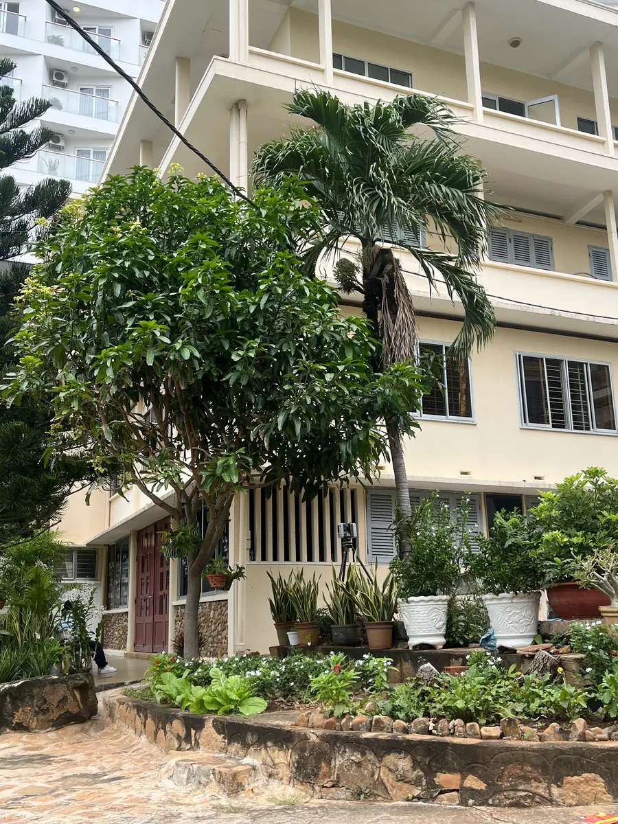
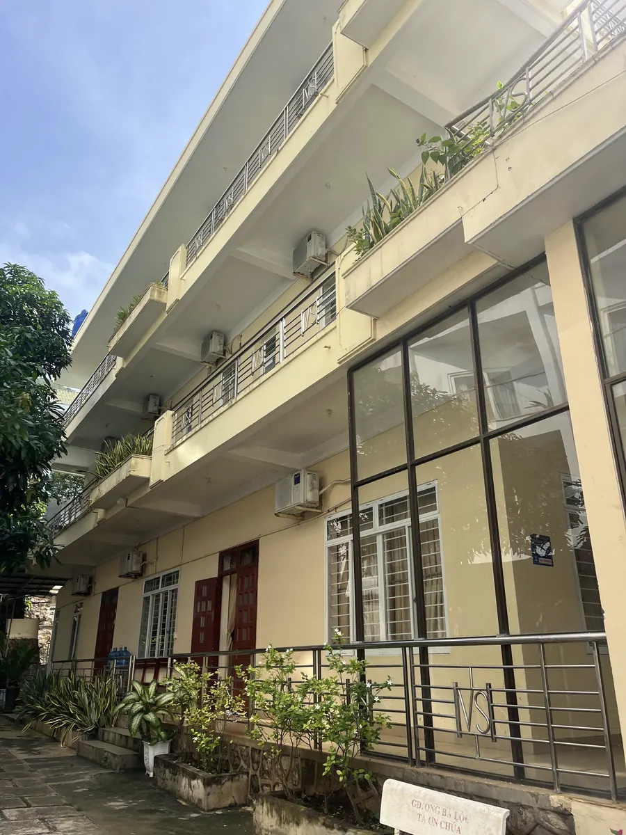
Spaces to be surveyed for the renovation design
7 photos · swipe →
Measure the existing condition correctly before intervening
The Betania Bai Dau project shows how 3DSCAN surveys complex existing buildings: combining 3D laser scanning, static GNSS, levelling and UAV into one consistent survey dataset for renovation and repair. The approach suits buildings whose architectural character needs to be preserved when interventions are planned. 3DSCAN is headquartered in Ho Chi Minh City and carries out as-built surveys for projects in many provinces across Vietnam.
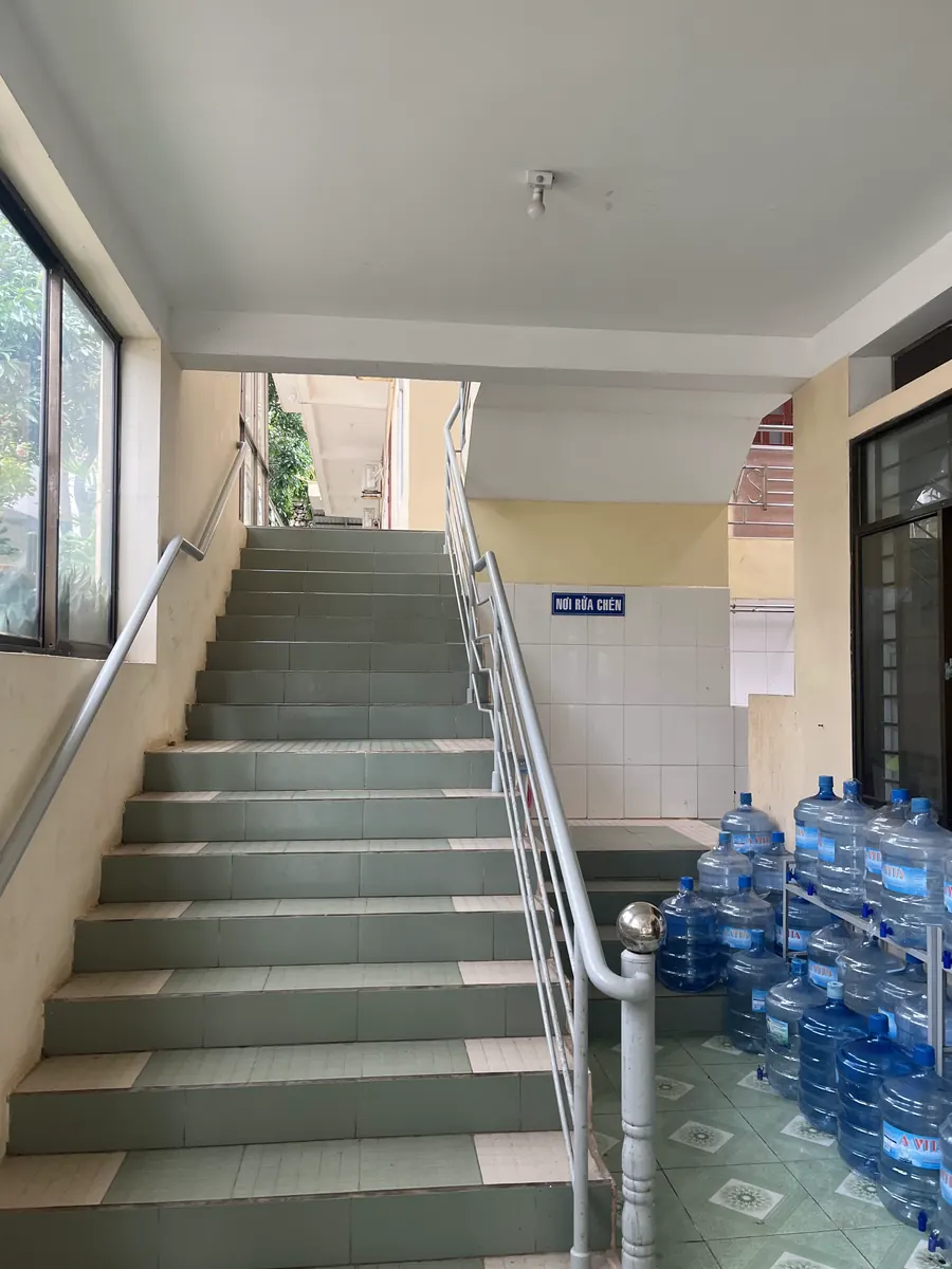
The building before renovation
4 photos · swipe →
Related projects and solutions by 3DSCAN
- 3D laser scanning of the existing building at 12 Vo Van Kiet, District 1: as-built data for an existing building in Ho Chi Minh City.
- As-built laser scanning for a building renovation: applied to a repair design package.
- Laser scanning for structural inspection of a 10,000 m² factory roof: roof geometry data supporting structural inspection.
- 3D laser scanning of St. Joseph's Cathedral, Hanoi: recording the geometry of a religious building.
Do you need an as-built survey of a church, a multi-level building or an existing structure before repair work? Contact 3DSCAN to discuss the survey scope and the data your design team needs.
Contact 3DSCAN Hotline: 0938 309 808 · Email: lienhe@3dscan.vn