

Laser Scanning for Structural Inspection of a 10,000 m² Factory Roof in Extreme Conditions
In structural inspection, every conclusion has to rest on a measurement someone else can verify, not on visual judgement. The difficulty in this project was that the entire steel truss system requiring inspection sat inside the roof void of a 50 × 200 m factory: dark, hot, cramped and crowded with obstructions, where conventional survey methods could deliver neither the point density nor the reliability needed. 3DSCAN carried out the measurement with a Leica RTC360 terrestrial laser scanner at 1.9 mm 3D point accuracy at 10 m range, capturing the full geometry of the structure to support the assessment of deflection and tilt and to identify the load-bearing system ahead of a rooftop solar installation.
Request a survey consultation for structural inspection
1. The problem: inspection measurement in a space that is barely accessible
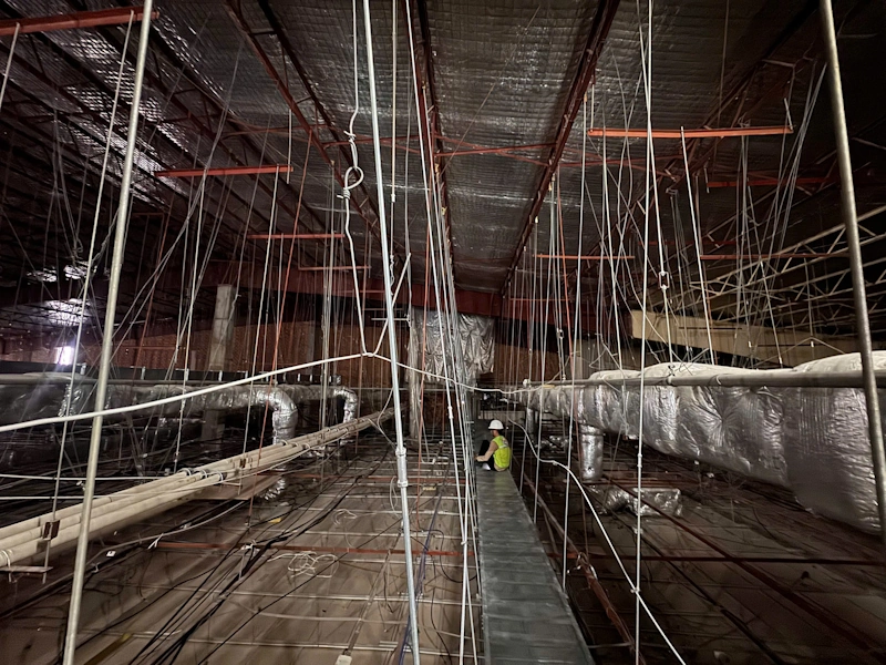
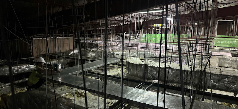
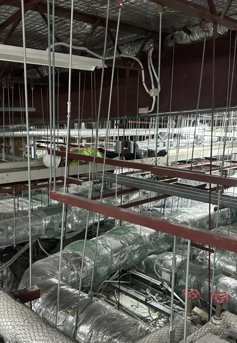
The building is a factory with a roof area of roughly 10,000 m² (50 × 200 m). The survey area lay in the roof void, the technical space between the ceiling and the metal roof sheeting, where the load-bearing steel truss system is located. Site conditions there combined nearly every adverse factor at once: walkways between truss members were severely restricted, so personnel and equipment had to squeeze through position by position; the area had no natural light, forcing the measurement method to work independently of illumination; the enclosed space under metal sheeting absorbed heat strongly, which directly limited safe working time; and trusses, cross-bracing and service pipework continuously created occlusions during measurement.
The inspection requirements, by contrast, were very specific. The client needed the existing load-bearing system identified precisely as the basis for designing the solar panel installation, together with an assessment of deflection and tilt in the steel trusses and the arched roof's supporting elements. These are quantities that must be measured numerically and accurately enough for a structural engineer to feed into calculations of additional load capacity.
2. Why only terrestrial laser scanning met the measurement requirement
The conventional approach for work of this kind is the total station. But a total station measures discrete points one at a time and needs a clear line of sight to each target, and both conditions are very hard to guarantee within the dense forest of cross-bracing in a roof void. More importantly, reconstructing the true deflection curve of a truss requires continuous data along the member; a few dozen discrete points are simply not enough.
Terrestrial laser scanning addresses exactly those two limitations. The instrument emits its own laser, so it measures in complete darkness; each setup scans a full 360° panorama and captures up to two million points per second, which means that wherever the scanner can be positioned, dense data follows for everything within view. Occluded surfaces are recovered by adding overlapping setups from different angles. Under the site conditions of this project, it was the only method that could both reach the space and produce enough data for structural analysis.
3. Measurement accuracy
a) Leica RTC360 specifications
The values below are the manufacturer's published specifications, stated at a 68% confidence level in accordance with the Guide to the Expression of Uncertainty in Measurement, JCGM 100:2008 (GUM):
Leica RTC360 technical specifications
| Parameter | Published value |
|---|---|
| 3D point accuracy | 1.9 mm @ 10 m · 2.9 mm @ 20 m · 5.3 mm @ 40 m |
| Range accuracy | 1.0 mm + 10 ppm |
| Angular accuracy | 18″ (arcseconds) |
| Acquisition rate | Up to 2,000,000 points per second |
| Range | 0.5 m – 130 m |
Because 3D point accuracy degrades with distance, the setup layout is always designed so that the members under inspection sit as close as possible to the nearest station. In a roof void, the distance from instrument to structure is typically under 10–20 m, which places the work in the instrument's best accuracy band.
b) Final data accuracy is not the same as instrument accuracy
This is a point 3DSCAN always states plainly to clients. The error in the delivered data is the combination of three components: the instrument's own error, the registration error between scan setups, and the error of the control network where the data must be tied to a project coordinate system. Across a 200 m long building, it is the registration error accumulating along the run, rather than instrument error, that demands the tighter control. Processing therefore always includes registration error checking in Cyclone Register and independent verification by total station at selected locations, so that the accuracy figure quoted in the report is a figure backed by evidence.
4. What inspection data can be extracted from a laser scan
A sufficiently accurate point cloud allows almost any geometric quantity of the structure to be re-measured on the computer, with no return trip to site:
- Deflection of trusses and purlins: the true member axis is reconstructed from the point cloud and compared against the theoretical straight line between supports, giving deflection values at any position along the span.
- Tilt of columns and frames: the measured member axis is compared against true vertical to determine displacement in both directions.
- Overall geometry: frame spans, bay spacing, ridge level and headroom clearance, all re-measurable at any time from the delivered data.
- Roof flatness and member positions: surface deviation against a reference plane, plus purlin and connection positions, forming the basis for selecting anchor points for the panel support frame.
- Clash detection and deformation monitoring: the model of the new system is overlaid on the as-built data to reveal conflicts before installation; a repeat scan at a later stage allows deformation to be tracked over time.
Do you need survey data accurate and verifiable enough to support a structural inspection report? 3DSCAN advises on a laser scanning approach matched to the accuracy requirements of each inspection item.
Contact 3DScan.vn Hotline: 0938 309 808 · Email: lienhe@3dscan.vn

5. Deliverables for the inspection file
Deliverables
| Deliverable | Use in the inspection |
|---|---|
| Point cloud (E57/RCP/RCS) | The raw measurement record, allowing any dimension to be re-checked later without a new survey. |
| As-built CAD drawings of the steel truss system | The basis for laying out the support frame and panels against the actual positions of load-bearing members. |
| Deflection and tilt report | Measured data for the structural engineer to assess the roof's capacity for additional load. |
| Data accuracy verification report | Documentation of registration error and independent check results, the element that makes the file auditable. |
Conclusion
For a space as dark, hot and confined as the roof void of a 10,000 m² factory, the Leica RTC360 terrestrial laser scanner is the solution that both reaches the site and produces measurements reliable enough for structural inspection. But the value of the report does not lie in the figure printed on the instrument's datasheet. It lies in the fact that the accuracy requirement is defined in advance, the error is controlled through processing, and the result is demonstrated by independent verification. That is how 3DSCAN approaches survey work on every industrial structural inspection project.
Does your facility have hard-to-reach spaces that need structural inspection before a solar installation or a refurbishment? Tell 3DSCAN the scale of the building and the accuracy your inspection body requires, and our engineers will propose a suitable approach.
Contact 3DScan.vn Hotline: 0938 309 808 · Email: lienhe@3dscan.vn