

Non-contact 3D laser scanning with the Leica RTC360: measuring where a tape measure cannot reach
In factories, hospitals, antenna installations and silos, whatever needs measuring tends to sit exactly where nobody can reach: pipe runs above the ceiling, equipment wedged between two operating machines, antenna mounts at the top of a mast, a silo shell curving from base to roof. 3DSCAN Technology Company Limited handles these areas with non-contact 3D laser scanning using the Leica RTC360: the scanner stands in a safe position and captures surfaces with a Class 1 laser at a 3D point accuracy of 1.9 mm at 10 m per the Leica Geosystems datasheet, each setup taking under two minutes. The point data then becomes sections, as-built drawings or 3D models used for renovation design and equipment installation. 3DSCAN operates out of Ho Chi Minh City and deploys to sites nationwide, usually alongside 3D laser scanning of architectural as-built conditions.
The hard part is not measuring — it is reaching what must be measured
A plant room rarely contains a single type of geometry. Planes, cylinders, curved runs, elbows and transition surfaces interlock, so the deliverable must describe both each object and the clearances between them — something a list of isolated dimensions cannot convey. Four constraints always appear together:
- No physical access: members at height, hard against running equipment, or inside a void that fits one person.
- Layered occlusion: no single standpoint ever sees the whole object.
- Small details: branch pipes, elbows and gusset plates are only identifiable when the data is dense enough.
- Restricted site hours: work has to fit around the client's production or operating schedule.
Picking equipment on one headline specification and improvising the rest is how a survey deliverable fails. The method has to answer all four constraints before anyone reaches the site.
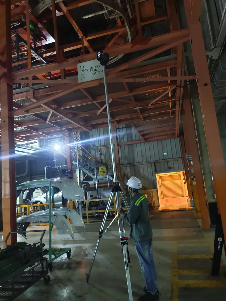
The rule that governs every scan: the instrument only measures what it can see
This is a physical limit of every laser scanner, not a weakness of one model. TSA guidance (Terrestrial Laser Scanning, Issue 5) notes that range, angle of incidence, surface characteristics and environmental conditions all affect data quality. Put differently, the 1.9 mm figure only means something for surfaces genuinely within line of sight — occluded areas have no accuracy to discuss, because they have no data at all.
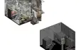
Setup 1 captures every surface within line of sight; the area behind the equipment block becomes an occluded zone and requires a fill-in setup from another direction. Pipework above a suspended ceiling cannot be captured by laser until the ceiling is opened.
The value of a survey therefore rests on two things done on site, before the instrument is packed away: accounting for every occluded zone and scanning the gaps. 3DSCAN agrees the list of objects to capture and the smallest detail to be identified before mobilising, checks coverage on the raw data on site, and only then moves to registration quality and the agreement between drawings and measured data during office processing. The deliverable states both results and the survey limitations — what was seen, what was occluded, which dimensions were cross-checked by independent measurement — so the designer knows which information can carry an engineering decision.
Set point spacing by the smallest detail, not by the finest setting available
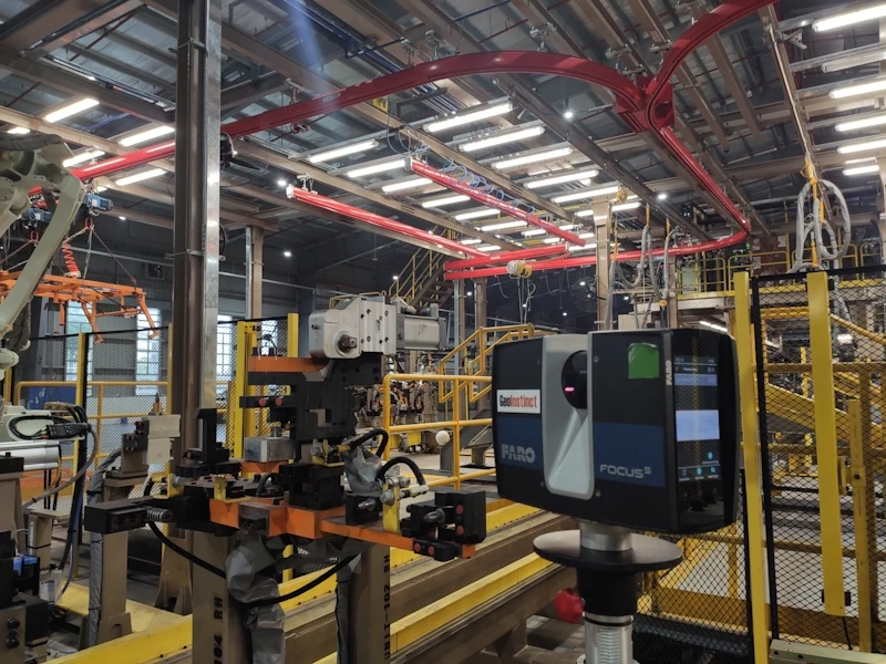
The RTC360 offers point spacings of 3, 6 or 12 mm at 10 m, captures up to 2,000,000 points per second, and completes a full dome scan with spherical HDR imagery in under two minutes at the 6 mm setting. That speed is not about finishing early; it is about having time left inside the permitted window to re-check thin coverage — something that cannot be fixed once the team has left. At 5.35 kg the instrument moves quickly between setups in tight spaces, and the VIS system pre-aligns point clouds on site so coverage can be monitored in real time.
Denser data means heavier files and longer processing, so over-specifying only slows the programme. 3DSCAN selects by situation:
Choosing the scan configuration by deliverable
| Deliverable required | Point spacing | Scanning range | Notes |
|---|---|---|---|
| Overall plant layout, silo volumetrics | 12 mm @ 10 m | Up to 130 m | Sufficient for general plans and sections |
| As-built records, Scan to BIM of structure and main pipe runs | 6 mm @ 10 m | 10–25 m | The setting used on most projects |
| Small branch pipes, elbows, connection plates | 3 mm @ 10 m | Under 10 m | More setups needed; files considerably heavier |
| Antenna members, elevated steelwork | 3–6 mm @ 10 m | 20–40 m | 3D point accuracy 2.9 mm @ 20 m and 5.3 mm @ 40 m; small distant parts may be under-sampled |
One point is easily misread: 1.9 mm is the instrument's accuracy, not the accuracy of the delivered drawing. The final product also accumulates error from registration, transformation into the project coordinate system and modelling itself. For dimensions that decide whether a component fits — equipment openings, soffit levels, clearance for a new pipe route — 3DSCAN cross-checks with independent total station measurement and records the result in the report, rather than citing the instrument specification.
“Instrument specifications only describe the best case. On site, what decides whether the deliverable is usable is where you can stand the scanner: a cramped plant room usually needs several extra setups purely to capture surfaces hidden by equipment, and that work has to be finished before the instrument comes down.”
— Phan Tien Duyen, Director, 3DSCAN
Four types of facility, four different setup strategies
Factories — answering “how much clearance is left”
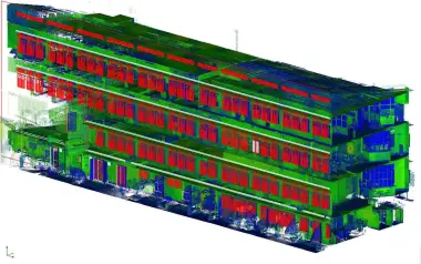
Pipework, cable trays, structure and equipment in a factory sit in layers. When a line is added or a service system is refurbished, the practical question is always how much clearance remains and what currently occupies the intended route. Scan data answers it with sections cut exactly at the installation area, the relative positions of each system, and a direct comparison of the new design against measured space. Congested areas always need more viewpoints than first assumed, so priority objects are checked on the raw data on site — before 3D model production from scan data or Scan to BIM at LOD 200–350 begins.
Hospitals — the operating schedule constrains more than the technology
Scope typically covers plant rooms, above-ceiling services and areas due for refurbishment, but what shapes the method is the facility's usage schedule and access rules. The workable approach is to split the site by zone and fix the object list and permitted working window in advance — precisely where an under-two-minute setup earns its place. For above-ceiling services, fully concealed sections must be flagged in the deliverable or surveyed by other means, never inferred in the model.
Antenna installations — capturing geometry without climbing to touch it
Antennas and their support frames consist of many members, brackets and components facing different directions, mostly at height. Non-contact scanning captures the visible surfaces without climbing to each member — a safety advantage, and no interference with transmitting equipment. What must be settled first is the objective: overall survey, locating principal components, or measuring connection details. Each level demands a different range and setup count, because at 40 m point density drops noticeably and a small component may not carry enough points to be modelled.
Silos — curved shells and transition geometry
A silo comprises a cylindrical body, roof, transition sections and ancillary parts — geometry that discrete point measurement can barely describe. Scan data allows sections to be extracted and compared against reference geometry; where the subject is the stored material, the same dataset supports 3D scanning for stockpile and volume calculation. Three points need agreeing beforehand: whether the scope is the outer shell or the interior, the operating state during measurement, and the purpose of the analysis. If the silo geometry genuinely changes while measurement is under way, a dedicated monitoring scheme is required — fast scanning does not make multi-setup data a snapshot of a single instant.
Deliverables
The list is agreed at the requirements stage, because the end product dictates point spacing and setup count — not the other way round:
- Registered point cloud (RCP/RCS, E57, LAS/LAZ, PTS) — for querying as-built conditions and re-measuring later without returning to site.
- 2D as-built drawings (DWG, PDF) — plans, sections, refurbishment documentation.
- As-built BIM model (RVT, IFC) — refurbishment design, pipe route clash checking.
- Surface mesh (OBJ, FBX, glTF) and 360° spherical imagery per setup — presentation and visual verification on the web.
- Technical report (PDF) — method statement, quality control results and survey limitations.
Conclusion
The right method starts from two questions, not from an equipment name: what will this data be used for, and how far does the site allow access. The Leica RTC360 is the answer when the work demands high capture speed inside a restricted window, point density sufficient for engineering detail, and flexible setup placement in confined space. 3DSCAN operates the RTC360 alongside SLAM scanners, UAV LiDAR, GNSS RTK and total stations, so several methods can be combined within one deliverable instead of forcing a facility to fit the limits of a single instrument.
Given site photographs, approximate dimensions, the list of objects to measure and the required deliverables, 3DSCAN can determine setup count, point spacing, fill-in positions and verification criteria — before quoting, not after mobilising.
Related projects by 3DSCAN
- Scan to BIM with underground utility detection — RMIT International University, District 7 — surveying an operating campus, both above-ground and buried services.
- 3D LiDAR scanning for buildings and facilities — scope of work, equipment and deliverables.
- 3D model production for the Tan Hue Vien resort — laser scanning combined with UAV for complex geometry.
- 3D laser scanning of architectural as-built conditions — standard workflow, QA/QC criteria and deliverables.
Need a factory, hospital plant room, antenna installation or silo surveyed without shutting operations down? Send 3DSCAN site photographs and the list of objects to measure — we will propose setup count, point spacing and verification criteria together with a quotation.
Contact 3DSCAN Hotline: 0938 309 808 · Email: lienhe@3dscan.vn