
3D LiDAR Scanning for Buildings: From Existing Conditions to Point Cloud, CAD and BIM
3D LiDAR scanning for buildings, also known as terrestrial laser scanning of existing conditions, uses a laser scanner to capture the geometry of a building or facility as a dense 3D point cloud. From this dataset, engineers can take measurements directly from the digital representation of the site, extract floor plans, elevations and sections, and develop CAD drawings or Scan to BIM models for design, renovation and facility-related applications.
In Ho Chi Minh City and projects across Vietnam, 3DSCAN applies laser scanning to factories, industrial facilities, existing buildings, architectural projects and renovation works. The value of the technology is not simply the number of points captured. More importantly, it creates a measurable and reusable digital record of existing conditions that can continue to support engineering and design work after the field survey has been completed.
Discuss Your 3D LiDAR Scanning Project
1. What Is 3D LiDAR Scanning for Buildings?
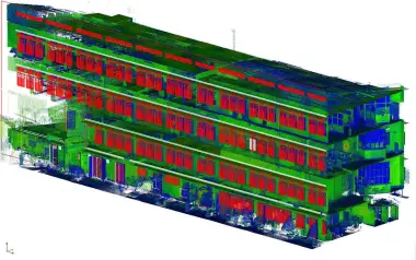
3D LiDAR scanning captures a large number of laser measurements in three-dimensional space and converts them into a point cloud. Each point contains XYZ position information and, depending on the equipment and acquisition method, can also be associated with photographic color information.
Unlike conventional methods that record selected dimensions or individual survey points, a terrestrial laser scanner captures a dense representation of the surrounding geometry from each scanner position. Multiple scan stations are then registered into a common coordinate system to form a unified point cloud of the building or facility.
PHYSICAL BUILDING → LASER SCANNING → POINT CLOUD → QA/QC → CAD / BIM / 3D MODEL → DESIGN & MANAGEMENT
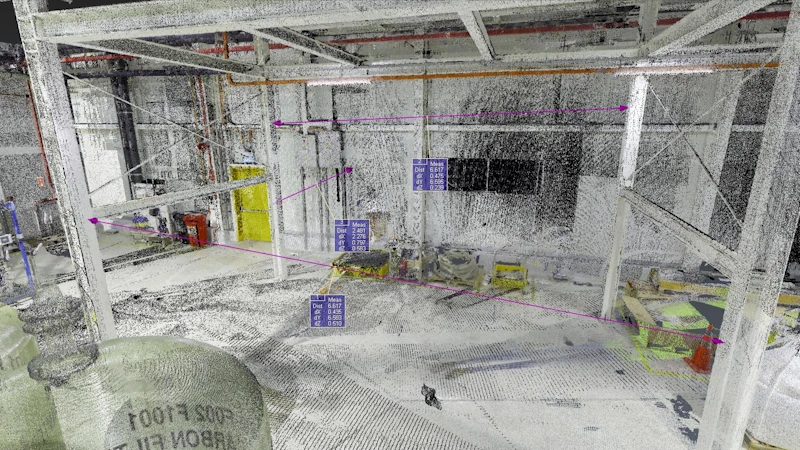
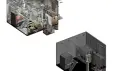
Point cloud captured with a Leica RTC360, providing the geometric foundation for measurement, CAD drawings and as-built BIM modeling.
For this reason, the output of an existing-condition laser scanning survey does not have to end with a point cloud. The dataset can be further processed into 2D drawings, BIM models or other 3D deliverables according to the project requirements.
2. When Should 3D Laser Scanning Be Used?
Laser scanning is particularly valuable when a building has complex geometry, contains many elements that need to be documented, or when reliable as-built drawings are incomplete or unavailable. It is also useful when the same survey dataset needs to support multiple engineering and design disciplines.
- Factories and industrial facilities: capture structural elements, architecture, equipment and MEP systems for renovation and engineering design.
- Existing buildings: develop floor plans, elevations, sections and digital as-built models.
- Renovation projects: provide architects and engineers with measurable existing-condition data before developing new designs.
- Scan to BIM: convert point cloud data into Revit/IFC models according to an agreed scope and Level of Development.
- Complex geometry: document roofs, steel structures, piping, equipment and areas that are difficult to represent with a limited number of conventional measurements.
- Heritage and historic architecture: record existing geometry using a non-contact measurement method.
3. 3DSCAN's 3D LiDAR Scanning Workflow
A reliable laser scanning project requires control of the entire data chain, from field acquisition to the final deliverable. Using a high-accuracy scanner alone does not mean that the registered point cloud or final BIM model will automatically achieve the same level of accuracy.
Step 1 – Define the Survey Objective and Scope
Before scanning begins, 3DSCAN identifies what the client actually needs: a registered point cloud, CAD drawings, floor plans, elevations and sections, a BIM model, or survey data for renovation design. The required deliverables influence scan density, site coverage and the way the final dataset is organized.
Step 2 – Plan the Scan Stations
Scanner positions are selected to provide sufficient overlap between stations and minimize occluded areas. Buildings containing multiple rooms, corridors, staircases, piping or equipment require a station layout adapted to the actual geometry rather than a fixed scanner spacing.
Step 3 – Acquire the Laser Scan Data
The scanner captures 3D data from each station. During fieldwork, the survey team checks coverage, occluded areas and connectivity between successive scans. Critical areas should be reviewed on site to reduce the risk of discovering missing data only after the field survey has been completed.
Step 4 – Point Cloud Registration and Control
Individual scan stations are registered into a unified dataset. Depending on project requirements, the point cloud can also be tied to a survey control network or project coordinate system. After registration, overlapping areas and potential alignment issues are reviewed as part of the quality-control process.
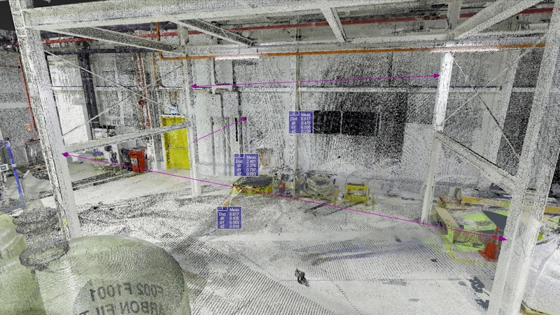
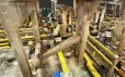
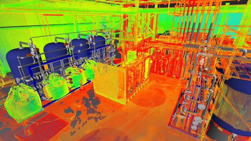
Industrial point cloud used for geometric verification and as the source dataset for the Scan to BIM process.
Step 5 – Clean and Structure the Dataset
Unnecessary data, moving objects and noise are handled according to the intended deliverables. The point cloud can then be organized by building, floor, area or discipline so that designers can work with the dataset efficiently.
Step 6 – Scan to CAD or Scan to BIM
Once the point cloud has been checked, it can be used to extract floor plans, elevations and sections or to develop a BIM model. In 3DSCAN's Scan to BIM workflow, the modeled geometry is checked against the original point cloud during QA/QC before final delivery.
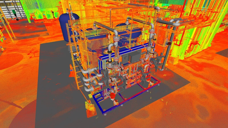
Checking the BIM model against the original point cloud is an important QA/QC step before delivery.
4. How Is the Leica RTC360 Used for Building Surveys?
The Leica RTC360 is a high-speed terrestrial laser scanner suited to existing-condition surveys of buildings, industrial facilities and projects requiring dense point cloud data. According to Leica Geosystems' published specifications, the RTC360 scans at up to 2,000,000 points per second, has a measurement range from 0.5 m to 130 m, and a published 3D point accuracy of 1.9 mm at 10 m.
LEICA RTC360 — MANUFACTURER SPECIFICATIONS
| Specification | Published Value |
|---|---|
| Scan speed | Up to 2,000,000 points/second |
| Measurement range | 0.5–130 m |
| 3D point accuracy | 1.9 mm @ 10 m · 2.9 mm @ 20 m · 5.3 mm @ 40 m |
| Selectable resolution | 3 / 6 / 12 mm @ 10 m |
| Field of view | 360° horizontal / 300° vertical |
Source: Leica Geosystems – Leica RTC360 Product Specifications. These values are manufacturer specifications for the scanner and should not be interpreted as guaranteed project-level accuracy.
An important distinction is that scanner point accuracy is not the same as final model accuracy. The quality of the final dataset also depends on scan-network geometry, registration, survey control, surface conditions, scanning distance, QA/QC and the subsequent modeling process.
5. Why QA/QC Matters More Than Scanner Specifications Alone
Laser scanning QA/QC must evaluate both the point cloud itself and the relationships between individual scan stations. A point cloud may appear visually correct while still containing alignment errors if registration or coordinate control has not been properly managed.
In practice, 3DSCAN reviews overlapping areas, planes and characteristic geometric features and, where required, compares the dataset with survey control. For BIM deliverables, quality control continues by comparing the modeled geometry against the original point cloud.
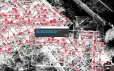
The RMIT District 7 Scan to BIM project is an example of combining laser scanning, topographic surveying and infrastructure information within a common dataset for renovation design.
6. What Deliverables Can Be Produced from a Point Cloud?
The point cloud is the foundation; the final deliverables should be selected according to how the client intends to use the data. Not every project requires a complete BIM model, and not every project should end with only the raw point cloud.
DELIVERABLES FROM 3D LASER SCANNING
| Deliverable | Typical Use |
|---|---|
| Point Cloud | Measurement, geometric verification and design reference |
| 2D CAD | Floor plans, elevations, sections and existing-condition drawings |
| BIM / Revit / IFC | Renovation design, architectural/structural/MEP coordination and building data management |
| 3D Models | Visualization, spatial review and integration with digital platforms |
BIM model developed from existing-condition laser scanning data for renovation design and technical coordination.
When the survey scope also includes terrain or the external environment, terrestrial laser scanning can be combined with UAV-based 3D topographic surveying or integrated UAV and laser scanning datasets.
7. 3D LiDAR Scanning vs. Conventional Existing-Condition Surveys
The key difference is not simply that “laser scanning is faster.” Laser scanning creates a dense spatial dataset that can be revisited to extract additional dimensions after fieldwork, whereas conventional measurement generally focuses on selected points and dimensions identified during the survey.
| Criteria | Selected-Point / Dimension Survey | 3D Laser Scanning |
|---|---|---|
| Data acquisition | Selected points or dimensions are measured | Dense 3D point cloud captured around each scanner position |
| Additional measurements | A return visit may be required if dimensions are missing | Additional dimensions can often be extracted from sufficiently captured areas |
| Complex geometry | Requires selection of representative measurement points | Surfaces are represented by dense sets of 3D points |
| BIM input | Information must be reconstructed from survey measurements | Point cloud can be referenced directly during BIM modeling |
Laser scanning also has limitations. The scanner records surfaces visible to the laser; occluded areas therefore require additional scan positions. Glass, reflective surfaces, moving objects and heavily obstructed spaces also require appropriate field procedures and quality control.
8. The Value of 3D Data for Design and Renovation
One of the main advantages of laser scanning is that it brings physical existing conditions into the digital design environment. Architects and engineers can evaluate spatial relationships between structures, architecture, piping, equipment and other existing elements rather than working only from a limited set of dimensions.
In industrial facilities, this data can support equipment layout and MEP design within an existing environment. For renovation projects, point clouds provide geometric reference before new design work begins. In BIM projects, the scan dataset becomes the geometric foundation for modeling and subsequent model verification.
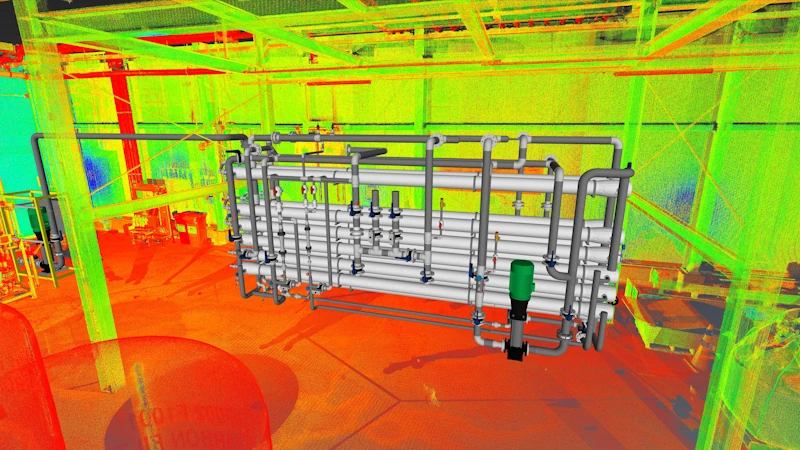
Laser scanning data can support detailed modeling of existing structural and MEP systems for renovation design.
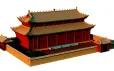
For historic buildings, the same data-capture principles can be extended to cultural heritage surveying and digitization, where the objective includes preserving an accurate geometric record for research and conservation.
9. Project Example: Laser Scanning and Scan to BIM in Ho Chi Minh City
The RMIT District 7 project demonstrates how laser scanning can become part of an integrated survey dataset rather than an isolated deliverable. According to the project information published by 3DSCAN, the overall site covered approximately 10 hectares, including approximately 35,000 m² of detailed Leica RTC360 scanning for renovation design and technical infrastructure purposes.
The laser scanning dataset was combined with topographic and underground utility survey information and subsequently integrated into the BIM workflow. This illustrates an important principle: the data-capture technology should be selected according to the final engineering and design requirements, rather than using laser scanning simply because a scanner is available.
10. Conclusion: The Point Cloud Is Only the Beginning
3D LiDAR scanning creates a digital foundation of existing conditions that can continue to support CAD, BIM, renovation design and building management. The value of the process is not in producing a large point cloud file, but in ensuring that the dataset has sufficient coverage, appropriate coordinate control, effective QA/QC and a clear path toward the technical deliverables required by the design team.
3DSCAN approaches laser scanning from a surveying and spatial-data perspective: selecting the acquisition method according to the required output, controlling registration, and structuring the dataset before converting it into CAD, BIM or other 3D products. Survey scope and level of detail should therefore be defined according to the technical requirements of each project rather than applying one scanning configuration to every building.
RELATED PROJECTS & SERVICES
- Scan to BIM, underground utility and topographic survey at RMIT District 7 — laser scanning for renovation design and existing-condition data management.
- Scan to BIM at the First Solar manufacturing facility in Cu Chi — laser scanning, point cloud processing and BIM modeling in an industrial environment.
- 3DSCAN Scan to BIM Services — from point cloud data to Revit/IFC models and technical drawings.
- 3D Laser Scanning for Existing Architecture — existing-condition data acquisition for design and renovation.
- 3D Modeling with UAV and Laser Scanning — combining multiple spatial-data sources for buildings and surrounding environments.
Planning an existing-condition survey for renovation, engineering design or BIM? 3DSCAN can work with your design team to define the scanning scope, required level of detail and final deliverables before fieldwork begins.
Contact 3DSCAN Hotline: 0938 309 808 · Email: lienhe@3dscan.vn