

3D scanning of industrial facilities with the Leica RTC360: fast capture, complete data, and project-wide accuracy control
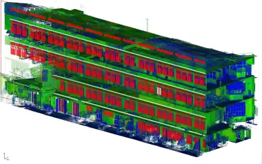
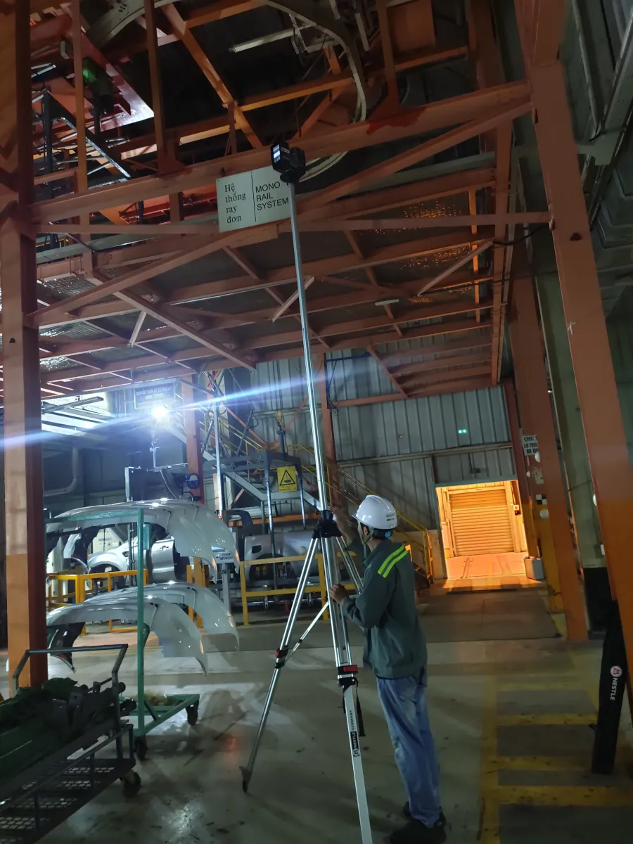
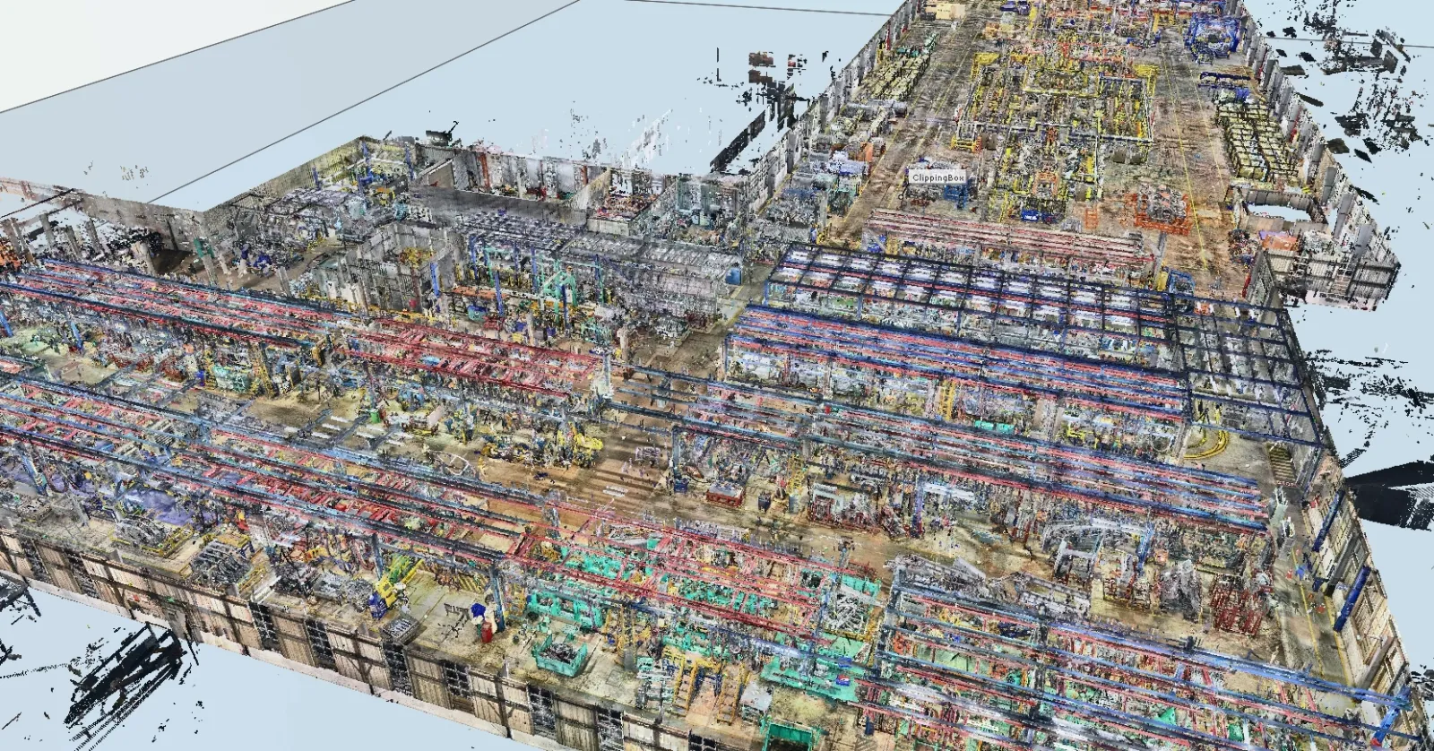
3D scanning of industrial facilities with the Leica RTC360 captures the complete as-built condition of a working factory — structure, machinery and building services — as point cloud data for renovation, new production line installation or MEP upgrades. The RTC360 delivers 3D point accuracy of 1.9 mm at 10 m and a maximum measurement rate of 2,000,000 points per second (Leica Geosystems datasheet), completing a full-dome scan with HDR imagery in under two minutes per setup. 3DSCAN Technology Company Limited — headquartered in Ho Chi Minh City — has used this exact instrument to survey 10,000 m² of unlit roof void and to deliver Scan to BIM for industrial plants at a model accuracy of approximately ±5 mm.
Request a facility survey consultation
1. In an industrial facility, "fast capture" only counts when the data is complete
A factory dataset is complete when it answers the actual design question, not when the point count is large enough. A new production line layout needs clear spatial dimensions, column positions and transport clearances. An MEP retrofit additionally needs the elevation and routing of pipework, cable trays and equipment within the intervention zone. These two requirements lead to two different scan station layouts.
Before mobilising to site, 3DSCAN agrees five points with the client:
- Objects to be captured: which structures, equipment and building services must appear in the deliverable, and which areas take priority.
- Smallest feature to be resolved: this determines the point spacing setting used on site.
- Required accuracy of the deliverable: the acceptance threshold for drawings and models — not the instrument specification.
- Areas requiring multiple viewpoints: multi-layer equipment clusters, pipe runs hidden behind beams.
- Deliverables: point cloud, 2D drawings, BIM model, quality control report.
Coverage must be assessed against the objects that actually matter. A project with billions of points can still have a data gap exactly where new equipment is due to be installed — and that gap usually surfaces only after the design team has started modelling.
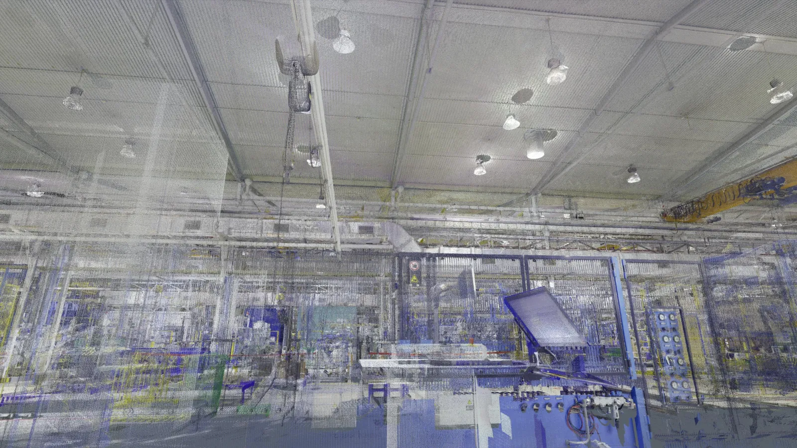
2. What the Leica RTC360 brings to a facility still in operation
The RTC360 suits industrial facilities for three measurable reasons: dense surface sampling, small point error at realistic working distances, and short occupation time on the shop floor. According to the Leica Geosystems datasheet, the instrument achieves 3D point accuracy of 1.9 mm at 10 m, 2.9 mm at 20 m and 5.3 mm at 40 m; three selectable point spacing settings of 3/6/12 mm at 10 m; a range of 0.5 – 130 m; and a Class 1 laser per IEC 60825-1:2014 — eye-safe, which is a precondition for scanning while operators are still working nearby.
The Visual Inertial System (VIS) tracks scanner movement between setups and pre-aligns the data in the field. In a multi-bay facility, the real benefit of VIS is not "automatic registration" — it is that the surveyor can see immediately which areas are not yet continuous and add setups before leaving site.
Published specifications: RTC360 versus BLK360 G2
| Published specification | Leica RTC360 | Leica BLK360 G2 |
|---|---|---|
| 3D point accuracy at 10 m | 1.9 mm | 4.0 mm |
| Finest point spacing at 10 m | 3 mm | 6 mm |
| Maximum measurement rate | 2,000,000 points/second | 680,000 points/second |
| Maximum range | 130 m | 45 m |
Source: Leica RTC360 and Leica BLK360 (G2) datasheets, Leica Geosystems. Specifications must be read together with each instrument's stated test conditions.
The 130 m range is the decisive specification for long-span facilities: from a single setup mid-bay, the RTC360 reaches the trusses, the roof and the gable wall in one scan, whereas a 45 m instrument forces the work to be split into many more setups — and every additional registration is another opportunity to accumulate error.
One point that most quotations omit: measurement rate does not determine project duration. Actual timing depends on movement between setups, access conditions, the volume of checking work and the data processing stage. The RTC360 shortens field capture; the rest comes down to how the survey is organised.
3. Capability demonstrated through completed projects
a. Structural assessment of a 50 × 200 m factory roof for a rooftop solar installation
The client needed to install a rooftop photovoltaic system on a factory roof measuring 50 m × 200 m, roughly 10,000 m², but no reliable structural records remained. The brief was to establish the actual load-bearing system and to assess the existing deflection and tilt of the steel trusses and the arched roof support system before calculating the additional panel loading.
The entire survey had to be carried out inside the roof void: no lighting, high temperature, confined space, and access routes obstructed by bracing and services. These conditions rule out most conventional methods — tape and total station cannot reach enough points across a 200 m length, while short-range scanners would require an unworkable number of setups in that space. The Leica RTC360 was the only instrument in the 3DSCAN inventory capable of meeting these conditions, thanks to its 1550 nm laser that is independent of ambient light, its 130 m range along the length of the building, and under two minutes per setup — which matters when every minute in a roof void is a harsh working condition for the survey crew.
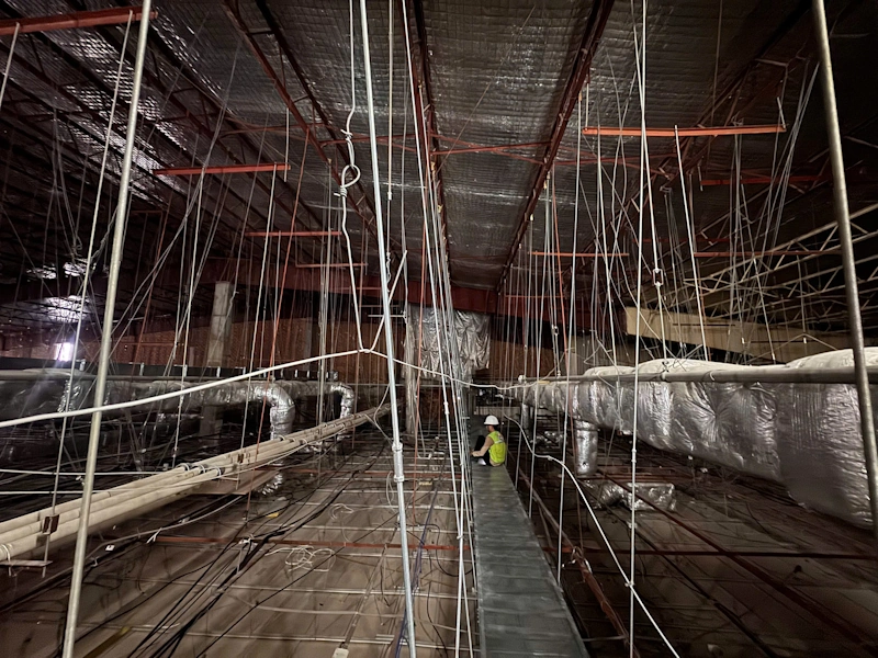
"In a roof void there is no light and no freedom to place the instrument where you like, so we do not select equipment from a catalogue — we select it from the site conditions. The RTC360 let us cover the full 200 m length of the building with a workable number of setups, and more importantly it let us spot on the spot which trusses still lacked data, so we could add setups before demobilising."
— Phan Tien Duyen, Director, 3DSCAN Technology Company Limited
b. Scan to BIM for the First Solar photovoltaic panel plant, Cu Chi
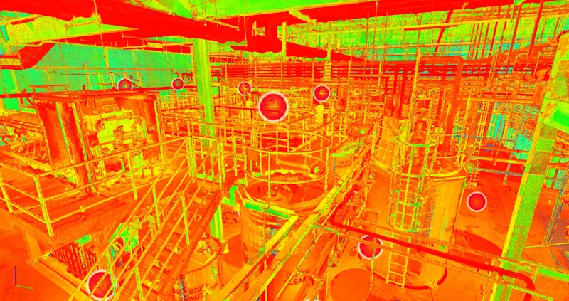
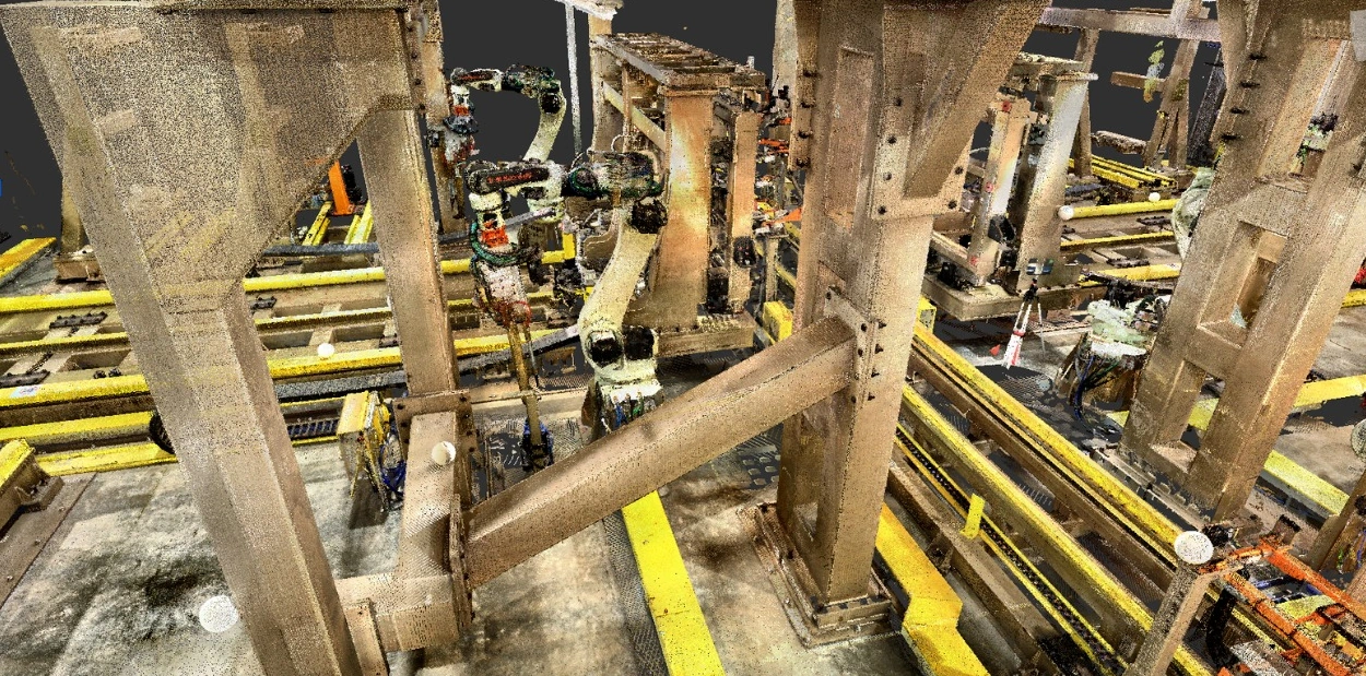
The Scan to BIM project for the First Solar plant in Cu Chi, Ho Chi Minh City was delivered to a target accuracy of approximately ±5 mm for the as-built model. This is a typical industrial case in which the point cloud must simultaneously cover the structural frame, high-level services and production line equipment — objects that occlude one another and cannot be re-measured once the line is running. The 3DSCAN Scan to BIM workflow uses Leica Cyclone for registration and Revit for modelling, typically at LOD 200–300 and reaching LOD 350 for industrial elements requiring higher detail.
c. 3D laser scanning of the INSEE Hon Chong cement plant, 120 ha
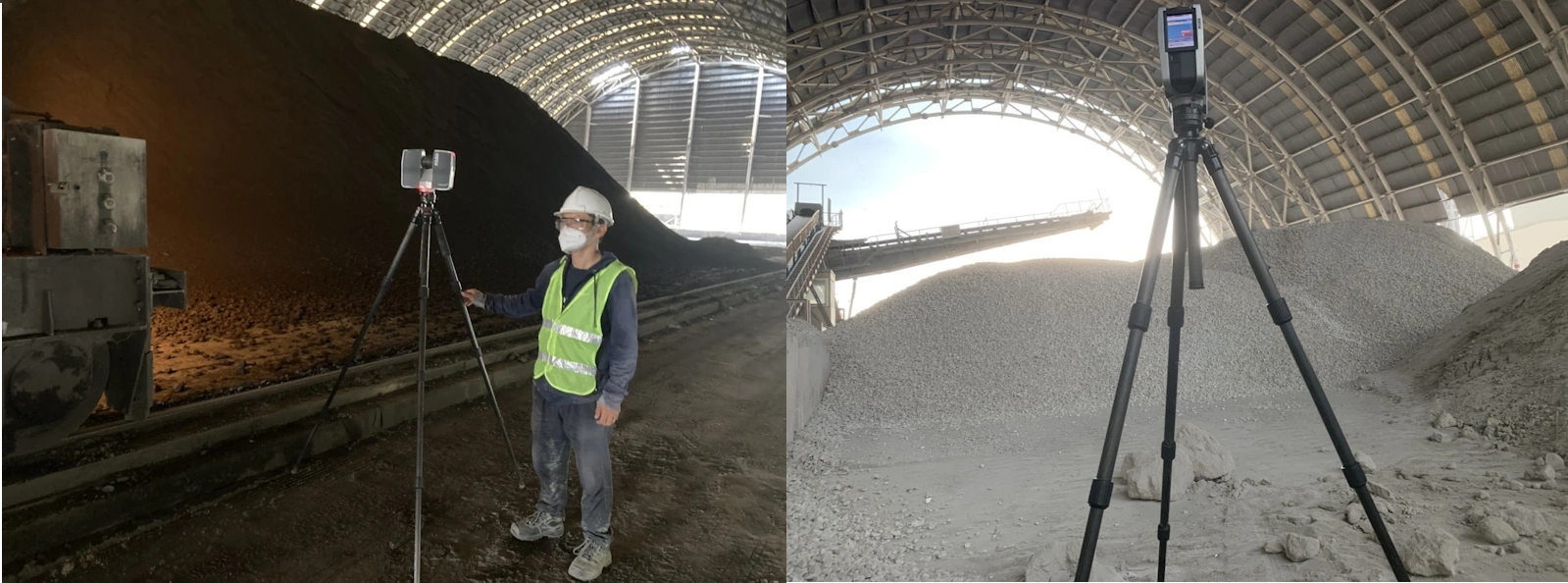
The 3D laser scanning project at the INSEE Hon Chong cement plant in Kien Giang covered 120 ha, combining terrestrial laser scanning indoors with UAV survey outdoors for periodic stockpile inventory of clinker, cement, limestone and the silo system. This project did not use the RTC360; it used a different equipment combination suited to volumetric work. What it does demonstrate is a capability equally relevant to factory clients: organising hundreds of scan setups inside a continuously operating plant, referencing everything to the VN-2000 coordinate system and delivering repeatable periodic reports. Selecting the instrument to fit the problem — rather than applying one scanner to every site — is a principle 3DSCAN applies consistently.
4. Setup planning and a single unified coordinate system
Planning setups to eliminate data gaps
The survey plan divides the facility into clearly related zones: production area, service corridors, plant rooms, mezzanines and relevant external areas. Within each zone, setups are positioned to face the surfaces that must be recorded — not distributed on a convenient regular grid.
The Survey Association (TSA) notes in Terrestrial Laser Scanning, Issue 5 that laser scanning measures only surfaces within the instrument's line of sight, and that setups must be registered and checked after capture. Field pre-alignment through VIS must therefore be accompanied by a data quality check, not replaced by it. 3DSCAN maintains a tracking sheet recording zones scanned, remaining gaps and the reason any area could not be reached; every gap that affects the design is resolved or formally reported before handover.
One coordinate system, one height datum
Industrial facilities typically have long footprints, multiple bays and zones surveyed at different times. All data must be referenced to a single coordinate system and a single height datum; otherwise the geometric relationship between the two ends of the building will be wrong even when each individual zone meets its tolerance.
Four items must be fixed at the start of the project:
- Origin, axis orientation and units — either a project grid or a client-specified system.
- Height datum in use — shared across every zone and every survey visit.
- Relationship to existing drawings or data — so the new model overlays correctly on legacy records.
- Transformation procedure between disciplines — structural, MEP and production line teams.
The control network and reference points are designed to match the scale of the survey. 3DSCAN establishes control using a Leica TCR802 total station (2-second angular accuracy) and a Leica DNA03 digital level (0.3 mm/km with Invar staff) — consistent with TSA guidance in Measured Building Surveys, Issue 4: parts of a building must be tied into a common control framework rather than assessed as isolated measurements.
5. Accuracy controlled at four levels, not just at the instrument
A point accuracy of 1.9 mm at 10 m is an instrument specification, not a guarantee for the whole point cloud or the delivered model. Registration error reported by the software is likewise only one indicator, to be read alongside independent checks: a zone that registers beautifully in isolation can still be displaced within the overall geometry of the building.
Four levels of quality control for facility data
| Check level | What is assessed |
|---|---|
| Data at each individual setup | Surface quality, noise, gaps and capture conditions |
| Registration between setups | Agreement across overlap zones, risk of double surfaces |
| Project-wide geometry | Deviation at check points and the relationship between distant zones |
| Modelled deliverable | Position, dimensions and shape of the model against verified data |
The quality report produced by 3DSCAN states check point locations, method, results and acceptance criteria. Acceptance thresholds are agreed against the project purpose — tighter where equipment will be installed, looser where the data only provides spatial reference.
6. From point cloud to a model that reflects the real condition
Good input data can still be misrepresented during modelling, so this stage requires its own controls. After point cloud processing, 3DSCAN overlays the model on the point cloud and checks critical sections to identify discrepancies.
Seven steps from agreeing the brief to handover: step 3 scans with the RTC360 at 3/6/12 mm point spacing at 10 m, under two minutes per setup; step 6 builds the model at LOD 200–350.
Items that must be checked between the model and the point cloud:
- Primary structure: position and dimensions of columns, beams and slabs.
- Building services: elevation and routing of pipework and cable trays.
- Installation clearances: gaps between equipment and structure.
- Irregular geometry: zones that are uneven or show signs of displacement and deflection.
- Stated limitations: areas not observed and elements that have been simplified.
For curved or deformed elements — sagging trusses being the most common case in older facilities — the method of representation must be agreed against the intended use. Automatically straightening geometry to make the model look tidy erases exactly the information the client needs. And it is worth remembering: specifying an LOD is not sufficient to define the accuracy of an as-built model; LOD must be paired with a tolerance requirement and a defined object scope.
7. The deliverable package and what the client should prepare
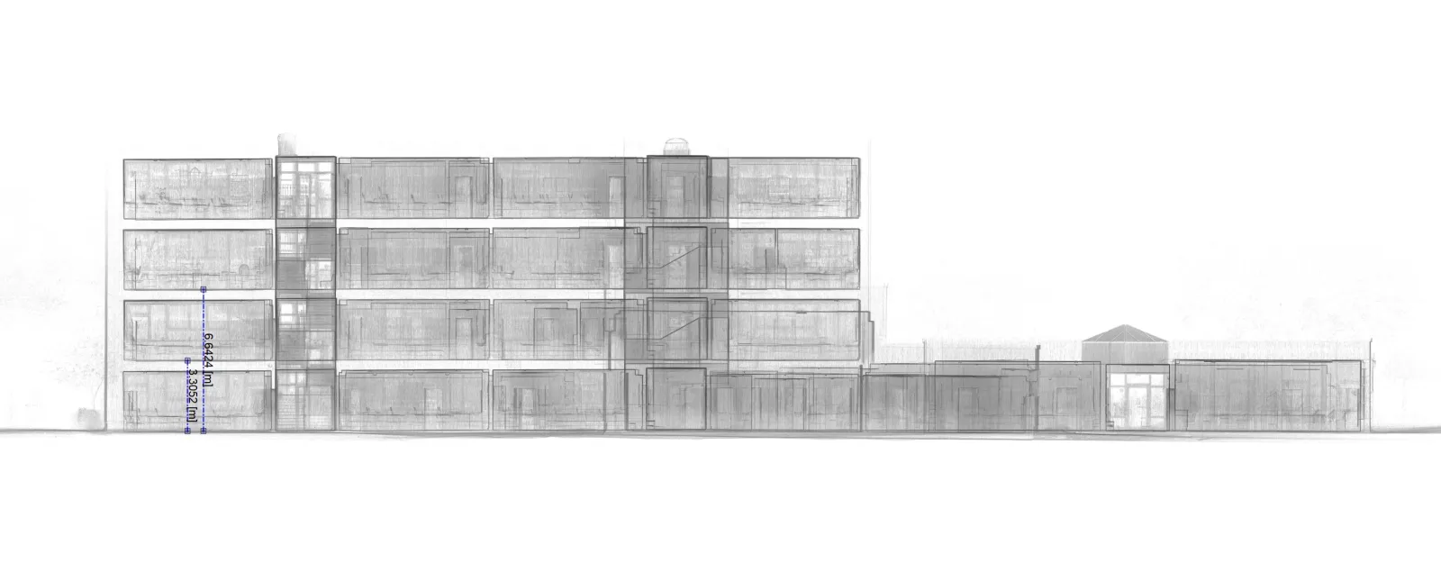
The deliverable package must tell its user what was captured, how it was tied together and how it was verified. Depending on the brief, it comprises the point cloud (LAS/LAZ/E57/RCP), plan and section drawings, the BIM model (RVT/IFC), a control network diagram, the quality control report and a register of areas with insufficient data. Extended deliverables such as VR360 or a browser-based 3D web viewer are added when the client needs to share data across multiple disciplines.
When discussing a proposal with 3DSCAN, clients should have four pieces of information ready:
- Purpose of the survey: renovation, line installation, MEP upgrade or structural assessment.
- Intervention scope: which areas will be modified and which only need spatial reference.
- Operating schedule: permitted access hours and any planned shutdowns.
- High-accuracy locations: equipment bases, flange faces, connection points.
8. What 3DSCAN has learned from industrial facility projects
Across the facility and plant projects delivered to date, 3DSCAN draws three practical conclusions. First, access conditions determine instrument choice more than catalogue specifications do — the unlit roof void on the 50 × 200 m project ruled out every option except the RTC360, while the 120 ha volumetric problem at INSEE Hon Chong called for terrestrial scanning combined with UAV survey. Second, a data gap always costs more than one additional setup: returning to a working factory usually costs more than a day of crew time, before counting the risk to the design programme. Third, what clients are actually buying is not a point cloud but verifiability — a clear quality control report is worth more than an attractive accuracy figure with no stated method behind it.
3DSCAN Technology Company Limited is headquartered in Ho Chi Minh City and delivers 3D laser scanning of existing building conditions across provinces throughout Vietnam. For factories and industrial facilities we work to the principles set out above: fix the brief before mobilising, plan setups around real site conditions rather than a convenient grid, verify at four levels, and hand over a package complete enough for a third party to check our work.
Related projects by 3DSCAN
- 3D laser scanning of the INSEE Hon Chong cement plant — 120 ha, periodic clinker stockpile and silo inventory.
- Scan to BIM with underground utility detection — RMIT International University, District 7 — above-ground conditions and buried services in one coordinate system.
- Scan To BIM service — Cyclone and Revit workflow, LOD 200–350, RVT/IFC deliverables.
- Laser scanning of existing conditions for building repair — deliverables and accuracy thresholds by method.
Do you need an as-built survey of a factory or industrial facility for renovation, production line installation or roof structure assessment? Send 3DSCAN the purpose of the survey, the intervention scope and your operating schedule — we will propose a Leica RTC360 capture plan with defined acceptance thresholds and a specific list of deliverables.
Contact 3DSCAN Hotline: 0938 309 808 · Email: lienhe@3dscan.vn